Turbo Electric Research Lab
One good example of current controllers and motors is the Toyota Prius.
To that extent Turbo Electric has acquired two Gen 1 Pruises to experiment and test.
This includes exclusive previously unreleased details of the Prius inverter.
The cars


The green Prius is a fully working road legal one with some minor damage to the front.
The white one is mechanically perfect but doesn't run.
It was sold under the presumption that it had a defective battery.
We managed to get the white one to do a few miles with the green car's battery, but suspect actually the petrol engine may be defective.
The HV batteries
Green Prius after HV battery casings were stripped away and reconnected.


This is still connected and powering the car normally.
The casings were removed to allow me to experiment with the battery easily.
This is the white car showing the battery removed (also the back seats) and dismantled.


The inverter
This is the white car's controller being dismantled


The IGBT block
The plan is to create a new controller for this Gen 1 Prius to make this an EV only car.
The motor(s) will need to be powered from this controller.
Since the expensive bits are already part of the car (motor, transmission, IGBTs, etc), it makes great sense to integrate the new controller into these parts.
The generator (MG1) IGBT block is a PM200CVB060.
The motor (MG2) uses a similar IGBT block which is more powerful, but electrically similar enough that either can be used for the new controller.
The driver boards for both IGBT packs actually have the same part number and they were swapped over on the green car and tested to make sure.
The plan is to use MG2 since this is geared directly to the differential and not through the CVT as MG1.
This will also be powerful enough for even motorway speeds, so no need to bother with MG1.
What this means is that experimentation can be done with MG1 and it's IGBT pack to debug the controller and electronics.
We can then use the fully debugged kit on MG2 and it's IPM.
Unfortunately, there isn't a datasheet on the PM200CVB060, but there is for a PM200CVA060, which going to be the same inside but with a different connector arrangement.
Luckily, the guys who made the driver boards put the pin assignments on it too, so it's just a case of following the wires to the pins on the IGBT pack and we complete the picture.
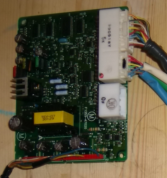
One of a pair of driver boards from a Gen 1 Prius Inverter.
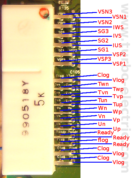
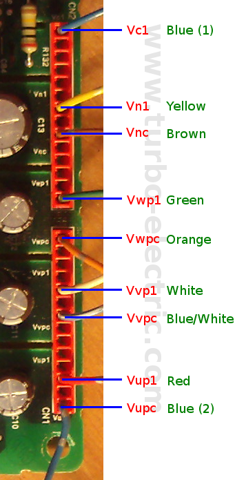
The IGBT connectors on the driver board.
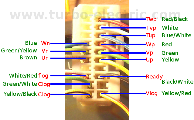
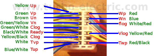
Pinout and wiring of the white connection.
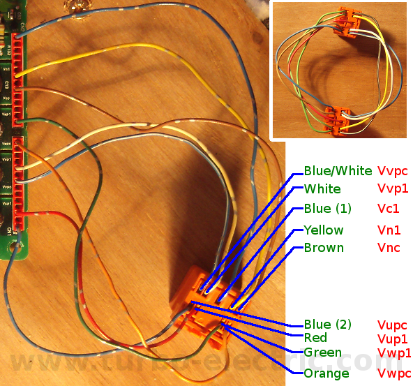
The Orange Plug connectors from the driver board.
The upper-right image is a plug to plug which shows a mirror pin mapping.
Full Pinout of the PM200CVB060 (previously unreleased)
�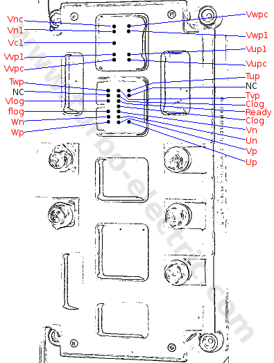
Full pinout of the PM200CVB060 IGBT Power Inverter Module which controls MG1.
This is the same pinout for the IPM, which controls the MG2.
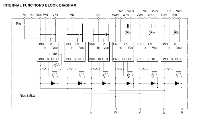
PM200CVA060 Block Diagram.
This can be now used for the PM200CVB060 also.
Another guy has been hacking at a Prius: http://www.techno-fandom.org/~hobbit/#prius
This site is worth a mention also: http://autoshop101.com/autoshop15.html


