The Mass EV Electronics Lab
Since we are building a new controller using the patent method of integrated (super- or ultra-) capacitors, we need to build the controller from scratch.
Simple relay-based controller
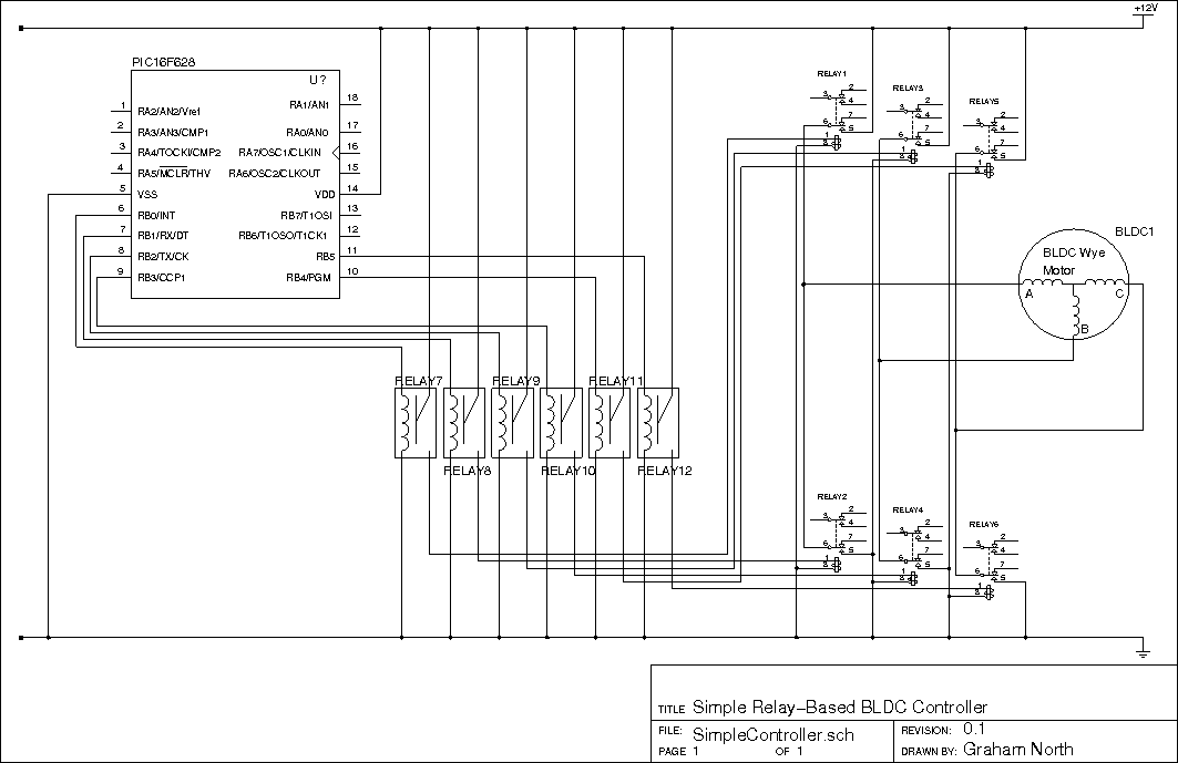
This is the first-principle controller using relays.
It helps to get the sequencing of the software without frying expensive components.
This very primitive model would even work when outputting PWM.
Or course, the relays will not using the AC synthesis, since they will just switch, but it will help to iron out a few early sequence and amplitude bugs.
Naturally the relays will be replaced with IGBTs (or an IGBT pack), but at £600 a pop vs less than £1 for the relays, which would you experiment with?
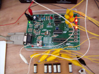
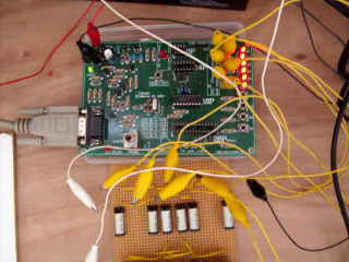
Here and Here are movies of it working.
May need fast connection to view.
Relay controller with transistor drivers
The next stage is to replace the driver relays with transistor equivalents

This is the transistor driver controller still using relays for output.
The transistors and resistor values were chosen since I had them already.
Previously, since we were using relays, we didn't need to now how much current was used in the parts of the circuit since relays aren't accurate components.
Now we are using transistors we really need to know so a few quick calculations are in order.
The PIC chip will provide up to 200mA at 5v so we need to know:
a) If the current is enough to drive the BC108C transistors with our pulldowns of 15k.
b) If the current from the transistors is enough for our relays.
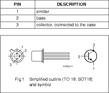
Pin Layout of the BC108C
The relays need 46mA and the BC108C can provide 100mA so that's OK.
The current required at the base of the BC108C is 92uA for the 46mA for the relays.
The current available at the PIC is 100mA which will easily provide the 425uA needed, so no probs.
Also: because we are using the transistor as a switch, rather than a relay, we need to be careful how the circuit is organised.
A transistor is a current amplifier so the voltages are irrelevant, but to switch the transistor on we need to make sure the base voltage is above the emitter by 0.7v.
The relay will switch on when the voltage difference is 12v across the coil.
This means if the relay is connected to the 0V it's other terminal which would be connected to the emitter needs to be 12v.
This means the base would have to be at 12.7v to switch it on, i.e. well above the 5v available from the PIC.
The simple answer is to put the relay coil in the collector circuit and ground the emitter.
This way the 5v from the PIC is well above the 0.7v now require at the base to turn the transistor on.
Split rail controller
There is an issue with using the above configuration; the MOSFETS I will be using are all N-channel.
These are the most common and because of this they are cheaper.
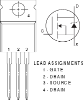
IRL2203N N-channel MOSFET
����
The previous circuit uses the common-emitter configuration and puts the outputs in the collector line.
This means we would have to use P-channel MOSFETS.
What we need is the ability to driver N-channel MOSFETs which require a voltage above the source pin.
In most motor controllers the control electronics is powered from a different supply than the motor itself.
Using a split rail supply, we could power the relays from common-collector transistors.
By connecting the positive battery terminal for the output to the ground of the controller, the output has a negative rail provided by the traction battery.
This means the drivers will always be positive of the outputs.
The issue here is the base current in the drivers, which will always be above the switch on voltage of 0.7v (from the negative now, not the ground).
We get around this using an opto-coupled driver which works more like a relay and has a completely separate switch (the LED) from the transistor.
�
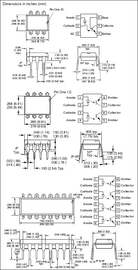
IL74 optocoupler
We just need to worry about the switch time which is usually in the order of 20uS (microsoeconds).
Given this is ultimately for a vehicle, the rotation speed is not going to be high.
A wheel of about 0.5m diameter would have a circumference of about 1.6m.
To travel at 200km / hour (which is 125mph) the wheel would rotate at 125,000 revs/hour or about 38 revs/sec.
Assuming a gear ratio of 10:1 (which is high for an electric vehicle, as some like the Tesla roaster are direct drive)
this means 380 rev/sec at the motor.
Assuming 60 poles at the stator which is 10 cycles this means we need 3,800 field rotations/sec.
For a brushless motor, each pole is switched twice for a rotation so we need 7,600 switches/sec.
The minimum period is therefore 1/7,600 sec = 132us which is well above our 20uS switch.
If this was the direct drive motors in the Tesla this would be going at 1,250 mph!
There is also the added benefit of having electrical isolation between the high power electrics and the sensitive control electronics.
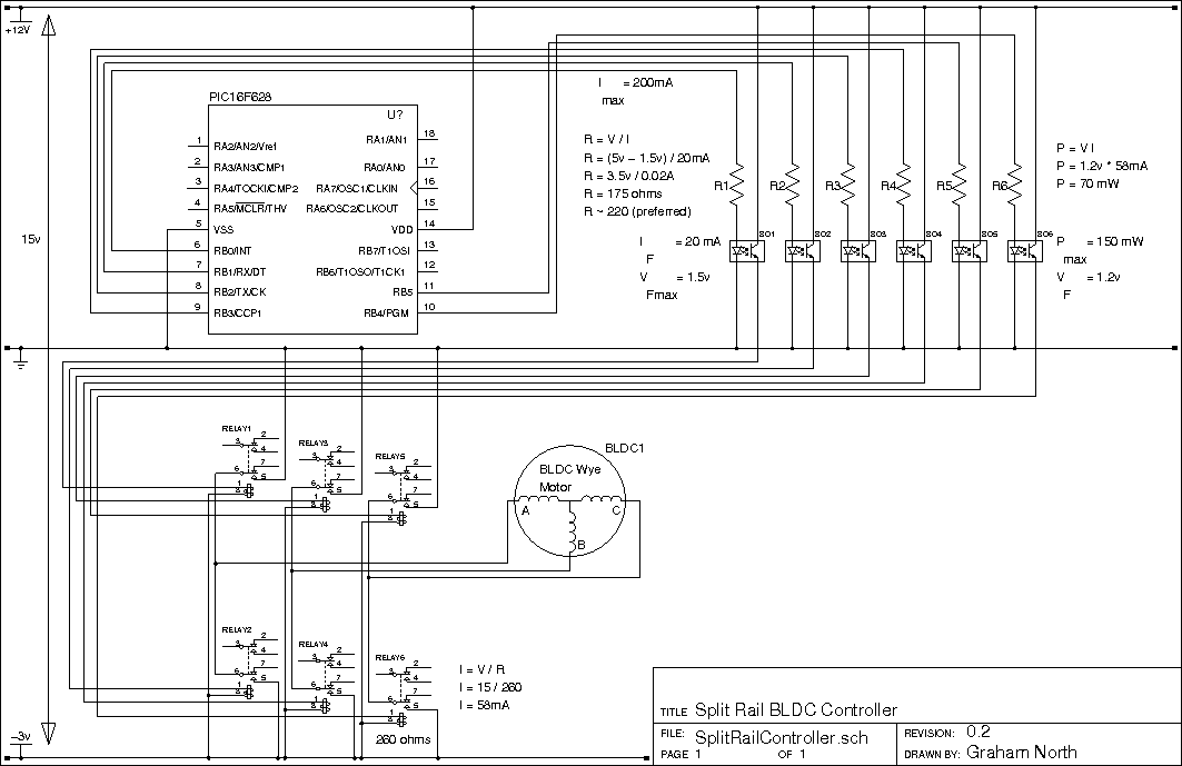
Split rail supply to drive relays using opto-coupled "common-collector" drivers
This would gives us the ability to power N-channel mosfets quite simply from the "common-collector" NPN drivers in the opto-couplers.
Solid-state controller
Now we have to replace the output stages with the solid state equivalents.
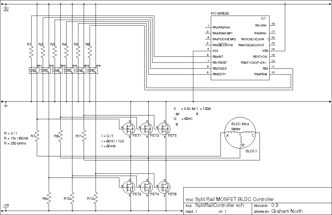
Solid-state split-rail controller using MOSFET outputs
In this case we are using MOSFET transistors.
MOSFETS are used because they are very good at using a very low power to control a high power.
MOSFETs work a bit differently to normal transistors in that they just need an electric field or charge on the gate to switch on.
It's like you need to think of the gate circuit like a capacitor and not a resistor.
This field is quite small, but needs to be above a certain voltage to switch it on.
So the speed of switching, not the amount of drain-source current, is determined by the gate current.
And the voltage on the gate determines the drain-source current.
If we say we want the MOSFET to turn on/off in 1 us (microsecond) this gives us the values of the switch off resistors.
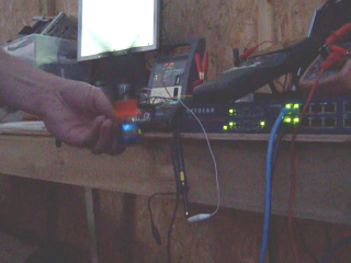
Here is a movie of it working.
May need fast connection to view.
IPM Controller
Here, since Turbo Electric Ltd has discovered the specification for the PM200CVB060 (also the PM600CVB060) IGBT power module used in the Toyota Prius,
we can use the controller to power the car directly.
This will obviously be currently in brushless DC mode and not AC synchronous mode as is used in the Prius.
That will come later.
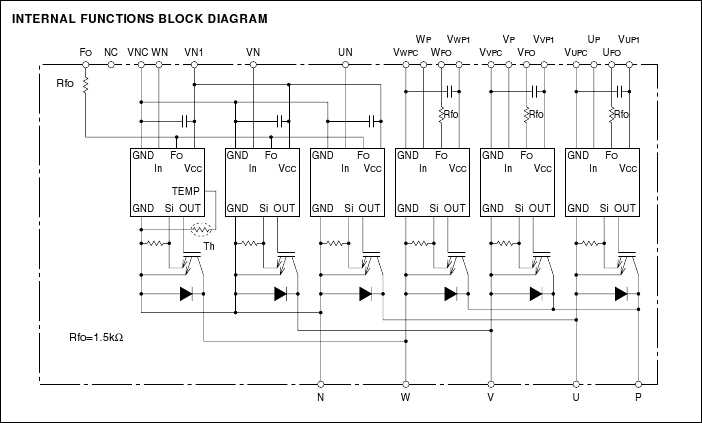
PM200CVA060 and PM200CVB060 Block Diagram.
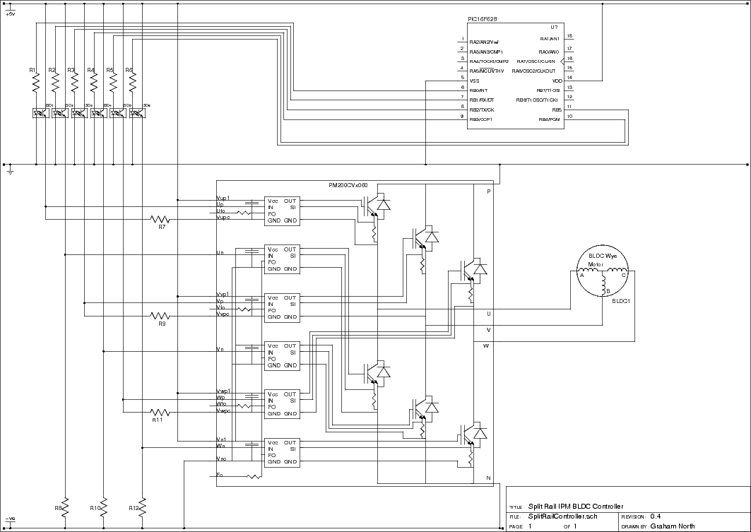
Split-rail controller diagram using the PM200CVx060 IPM.
Unfortunately I haven't got this to work yet.
Mitsubishi, the manufacturer of the IPMs, have produced a document on how to use their IPMs.
The PM200CVA060 is listed as one of the parts to which the document applies,
which means it should equally well apply to the PM200CVB060.
Here is a copy of the document.
This includes a diagram using opto-isoloators:
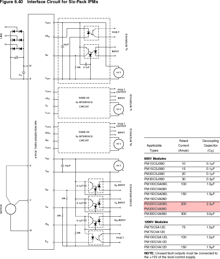
The inputs are inverted and the fault outputs need to be tied high to prevent false faults.
Here is the new diagram.
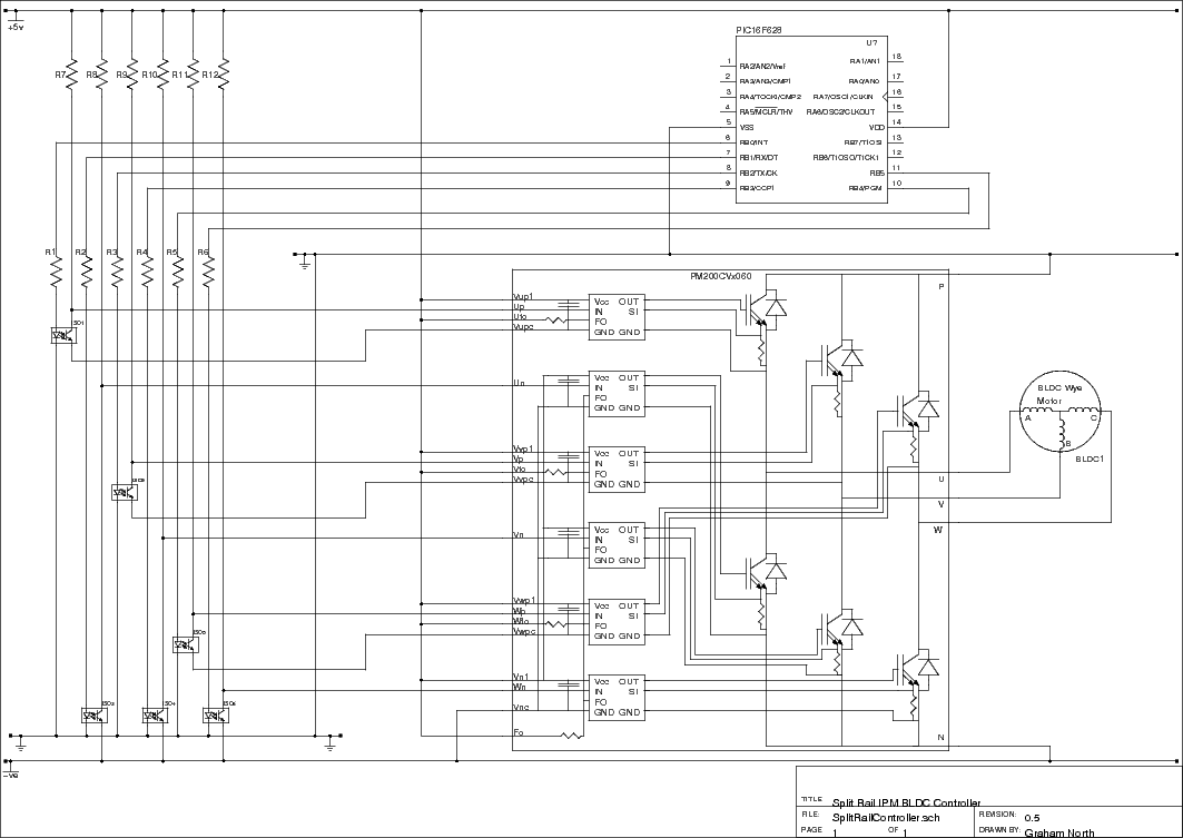
This means R7-R12 should be 20k (referring back to the Mitsubishi diagram)
There is an issue here in that the input voltage for the IPM controller side is quite limited.
If it is intended to use this on a high voltage system this will not work.
It may be possible to physically open the case and connect to the IBGTs directly, by passing the input circuits.
This means I will be able to implement the solid state FET circuit above, which has been tested and works.
Mitsubishi have obviously made assumptions about the kind of input circuits that this device is going to use,
however the single split rail input obviously reduces the complexity of using 4 or 6 separate isolated supplies (and the cost) by several orders of magnitude.
It is our belief that (like Einstein) things should not be complicated if it is possible to make them simple.
The "Solid-state split-rail controller using MOSFET outputs" circuit is indeed simple and it has been tested and works.
The only issue may be the gate-source voltage which could be beyond limits.
This can be restricted by inserting a resistor-zener diode circuit into the gate input circuit.
