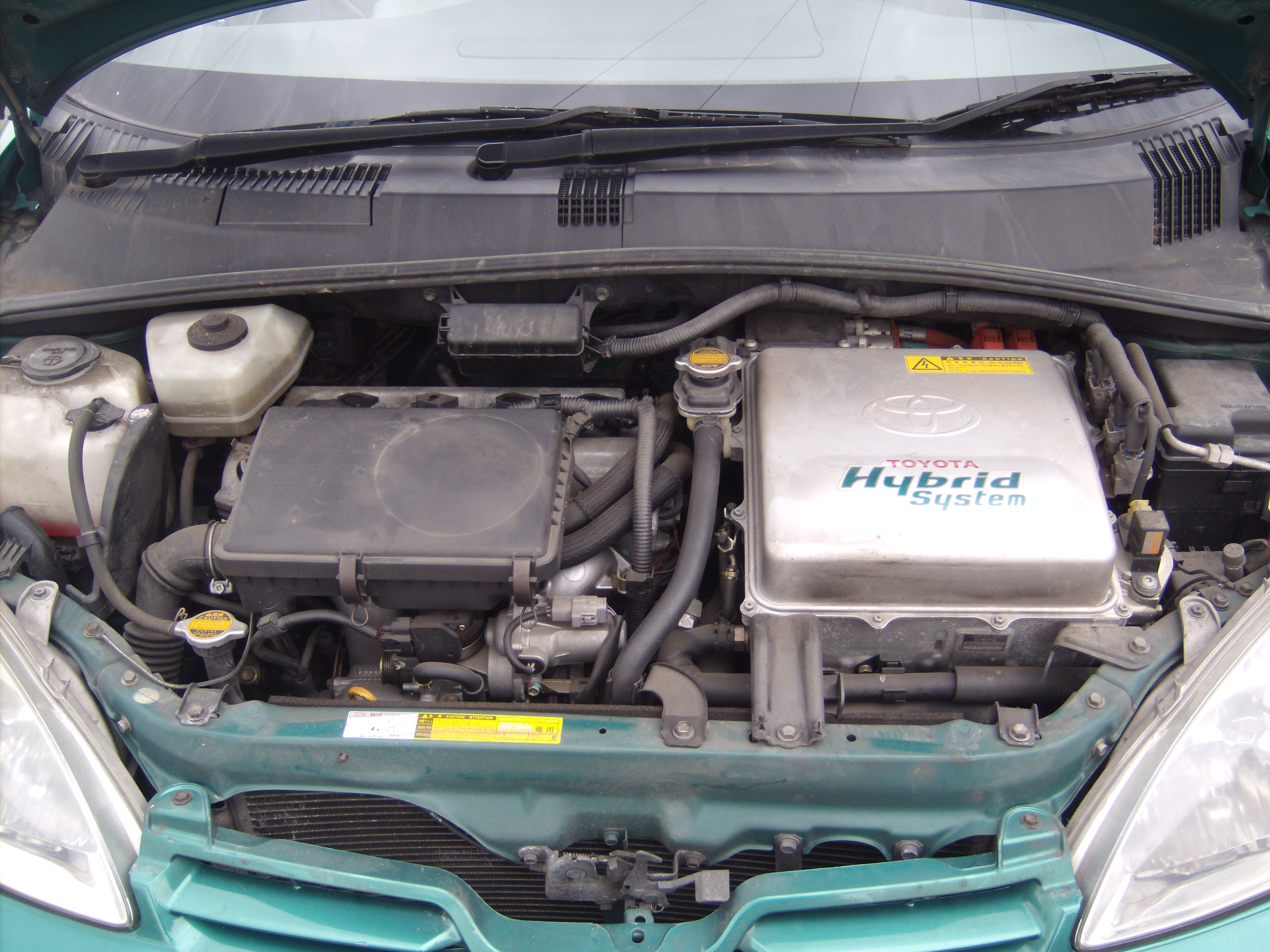
One good example of current controllers and motors is the Toyota Prius.
To that extent Turbo Electric has acquired two Gen 1 Pruises to experiment and test.
This includes exclusive previously unreleased details of the Prius inverter.
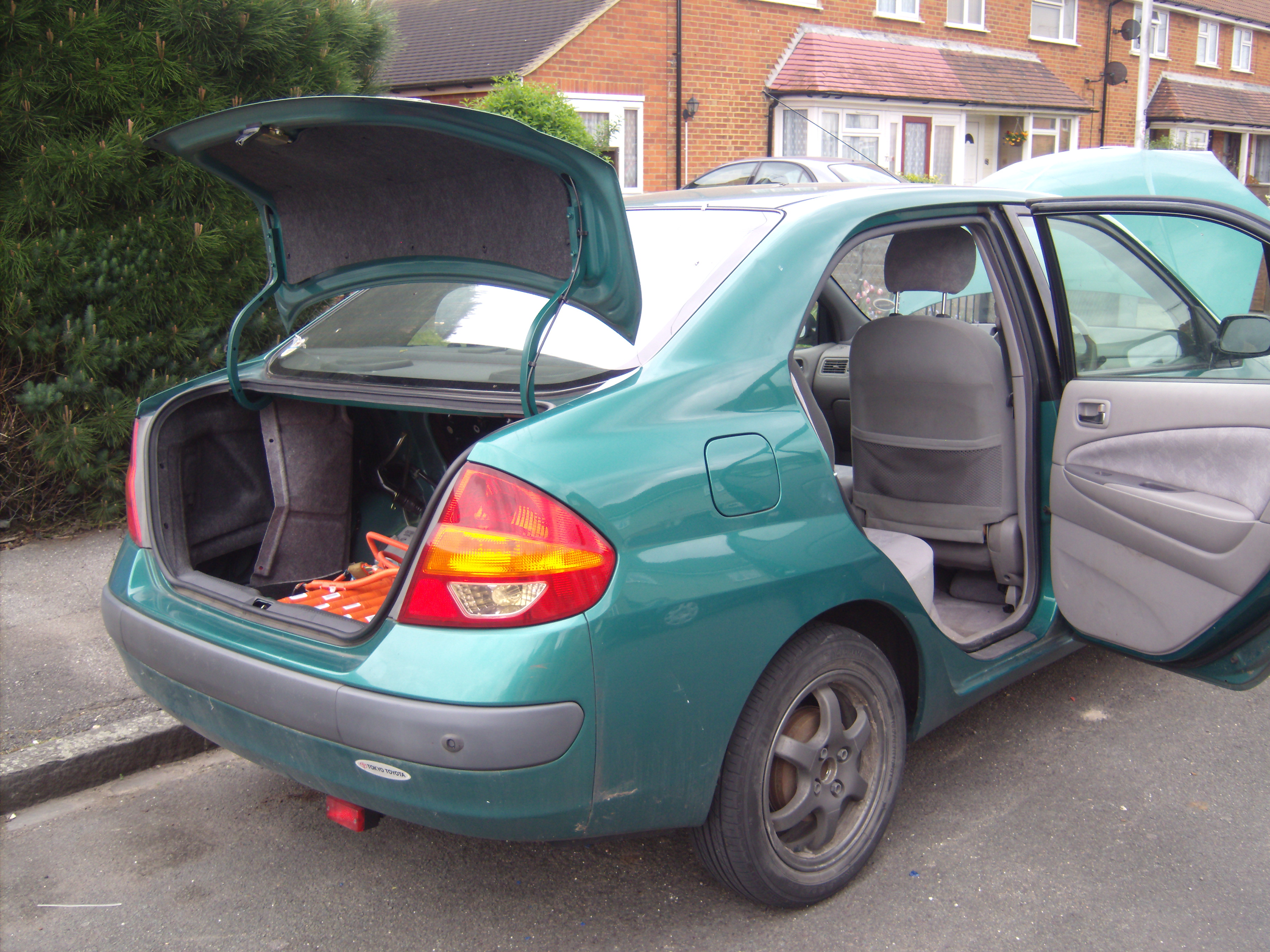
The cars
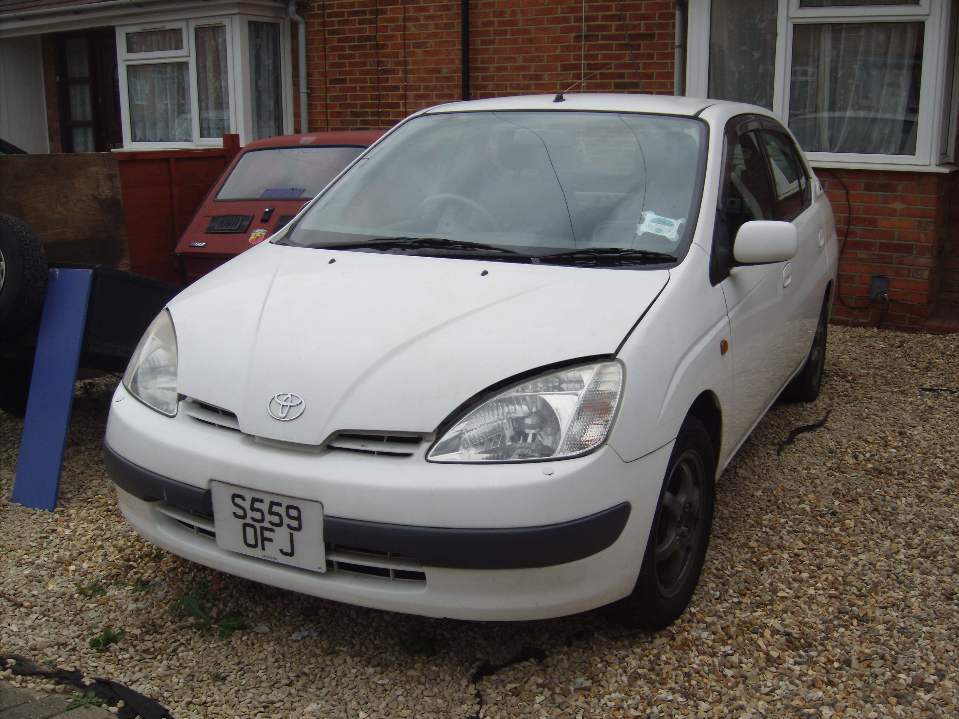
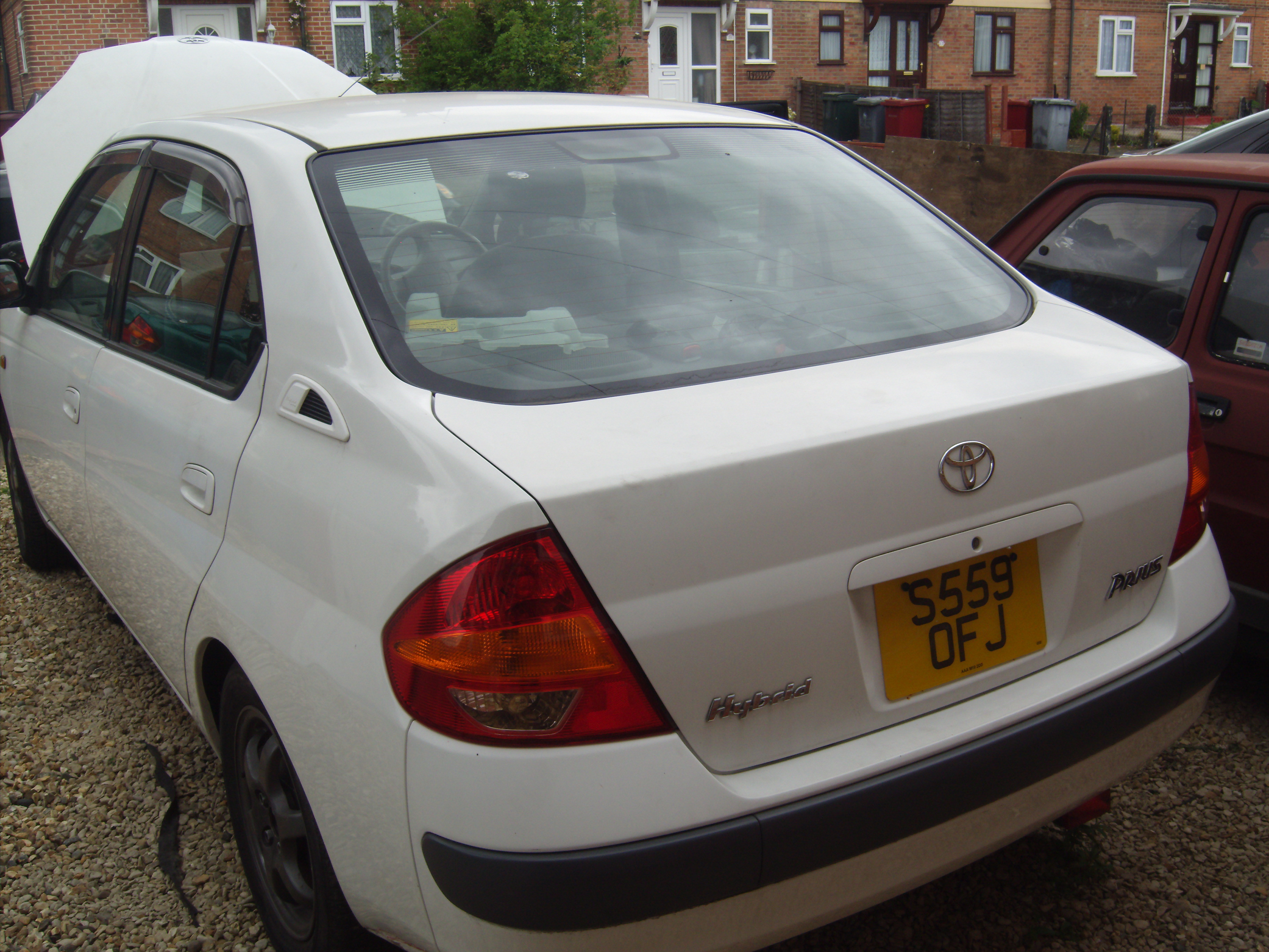
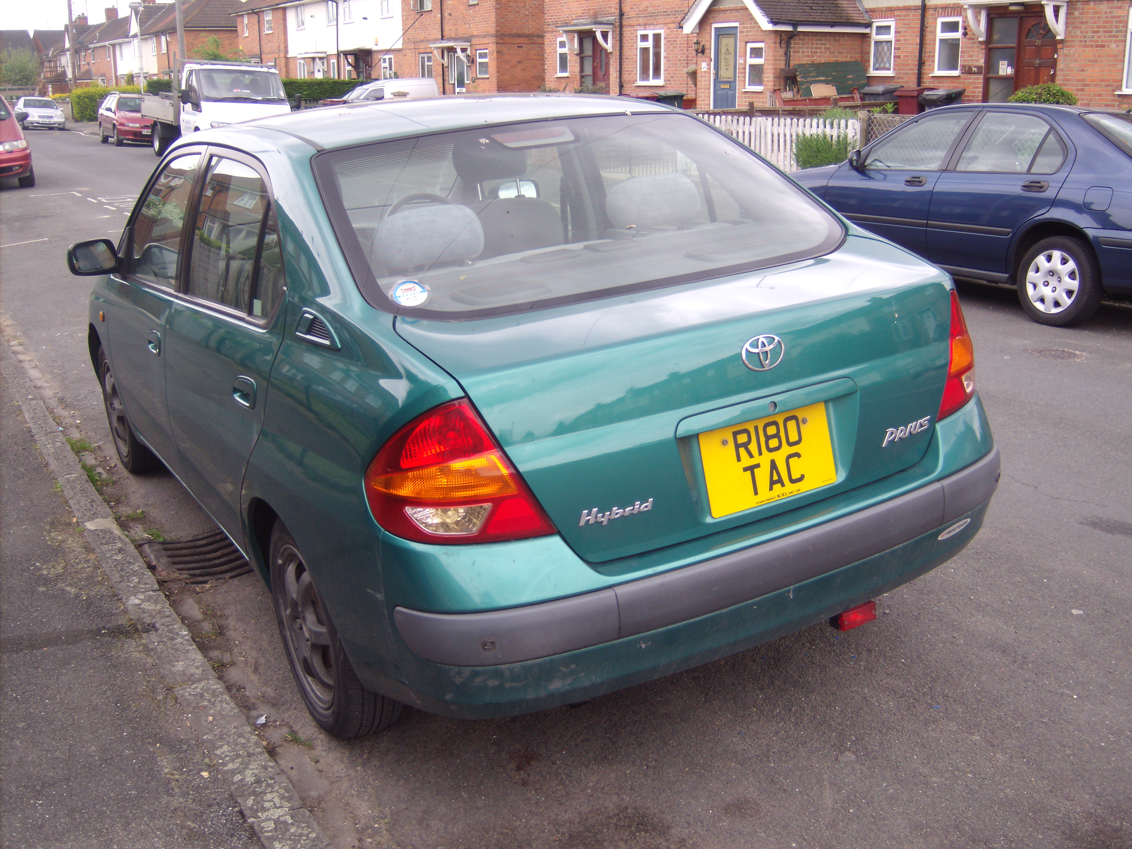
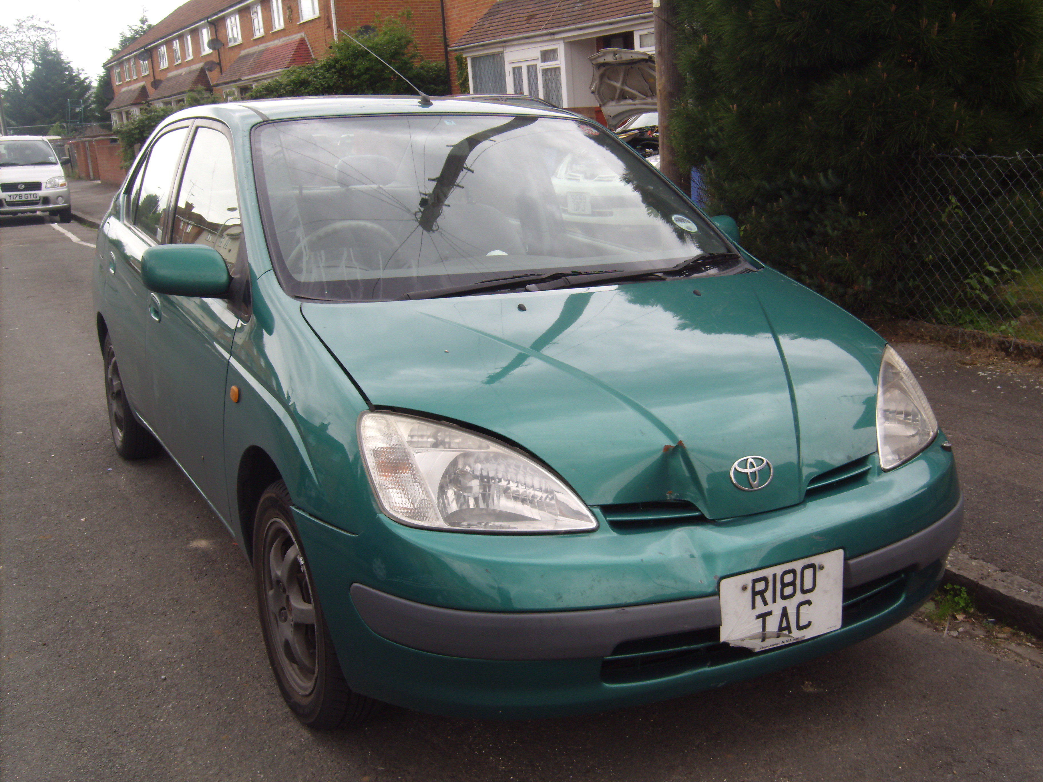
The green Prius is a fully working road legal one with some minor damage to the front.
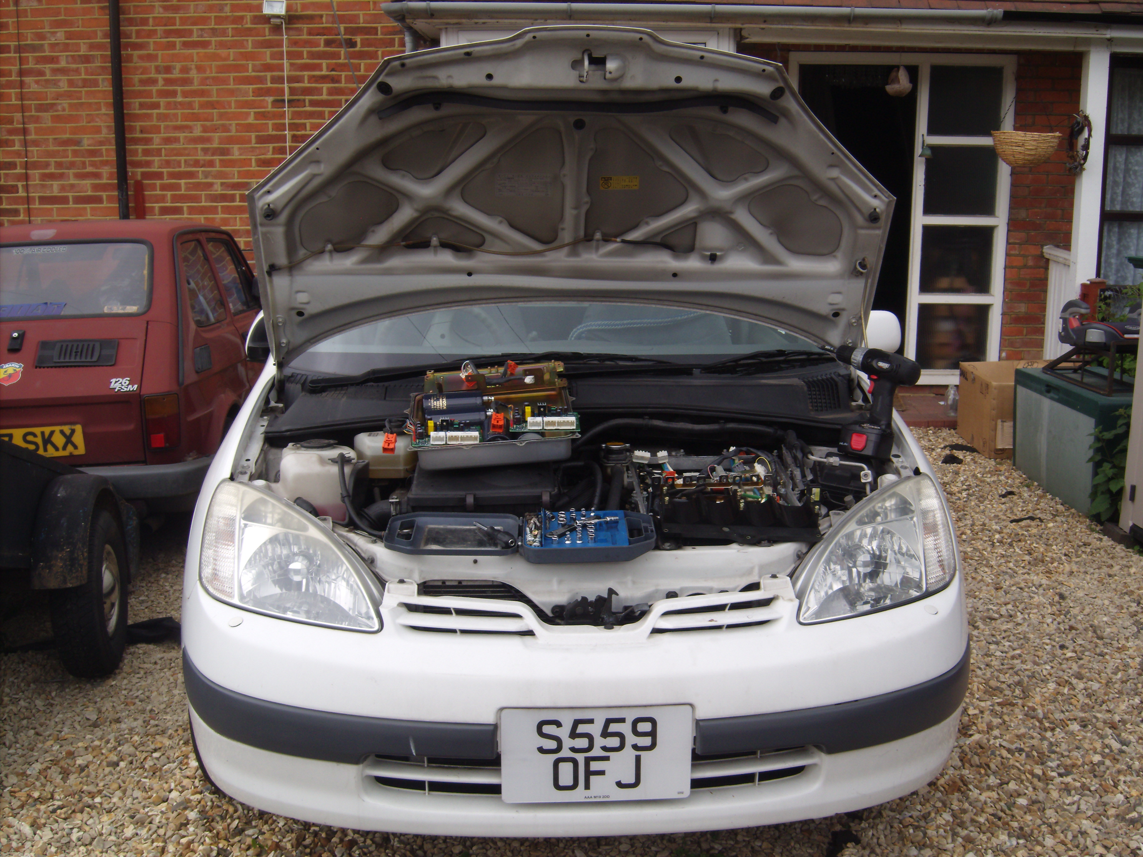
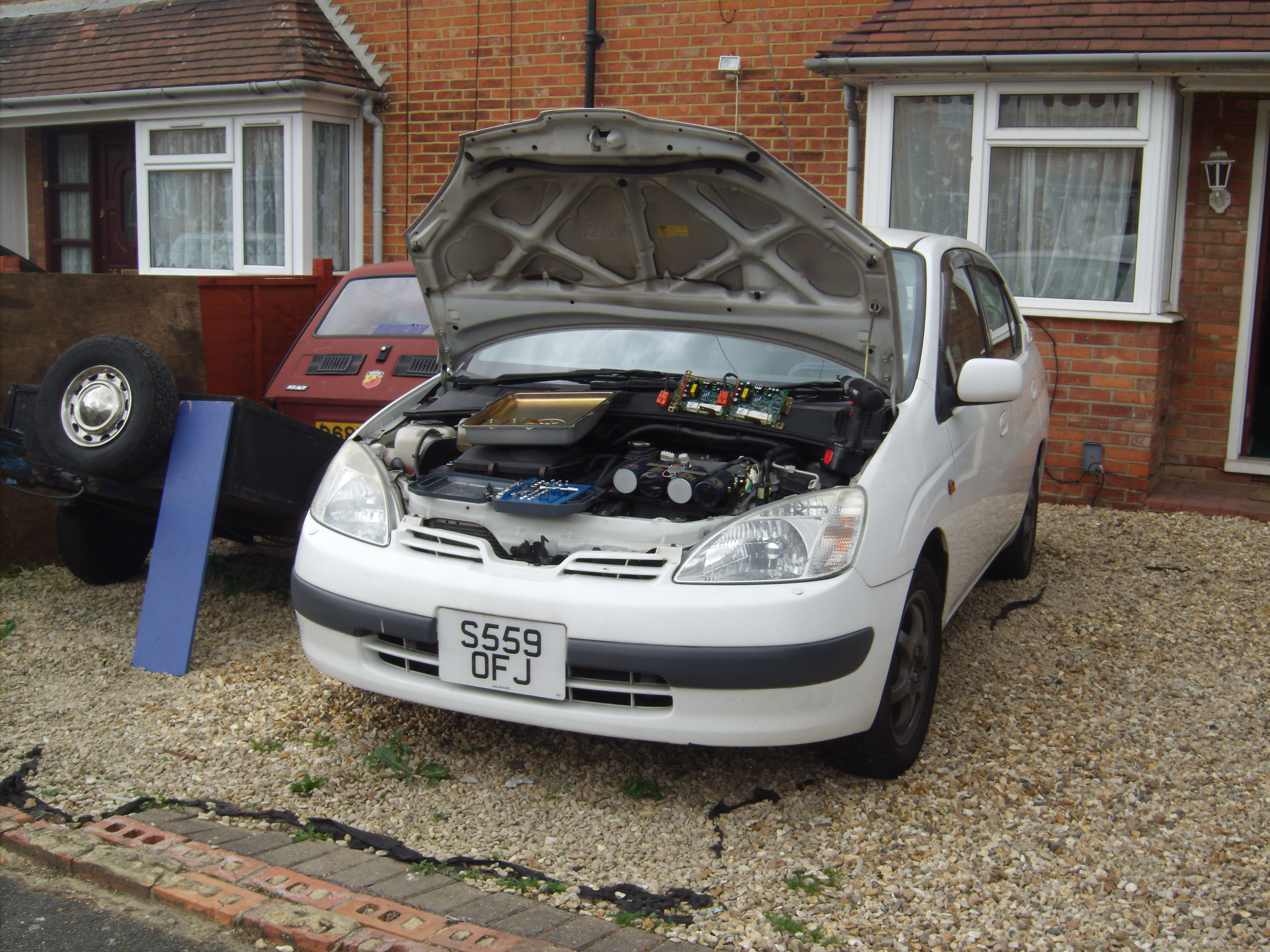
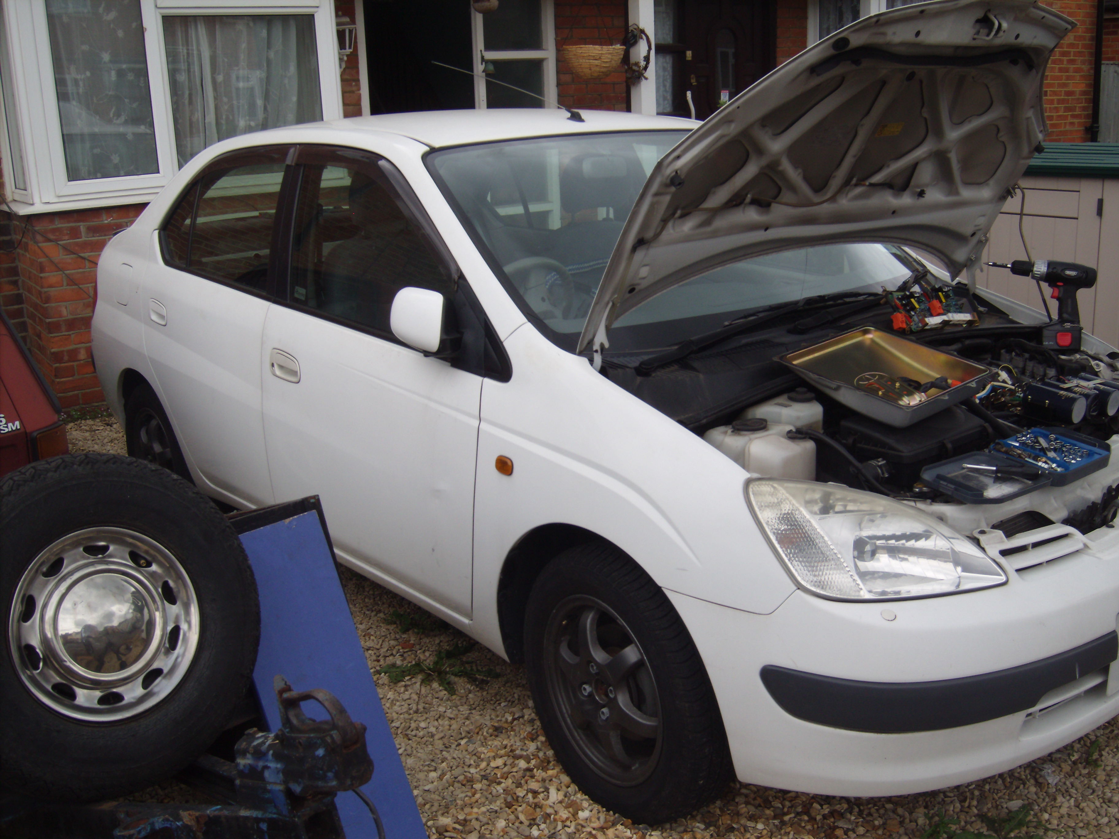
The white one is mechanically perfect but doesn't run.
It was sold under the presumption that it had a defective battery.
We managed to get the white one to do a few miles with the green car's battery, but suspect actually the petrol engine may be defective.
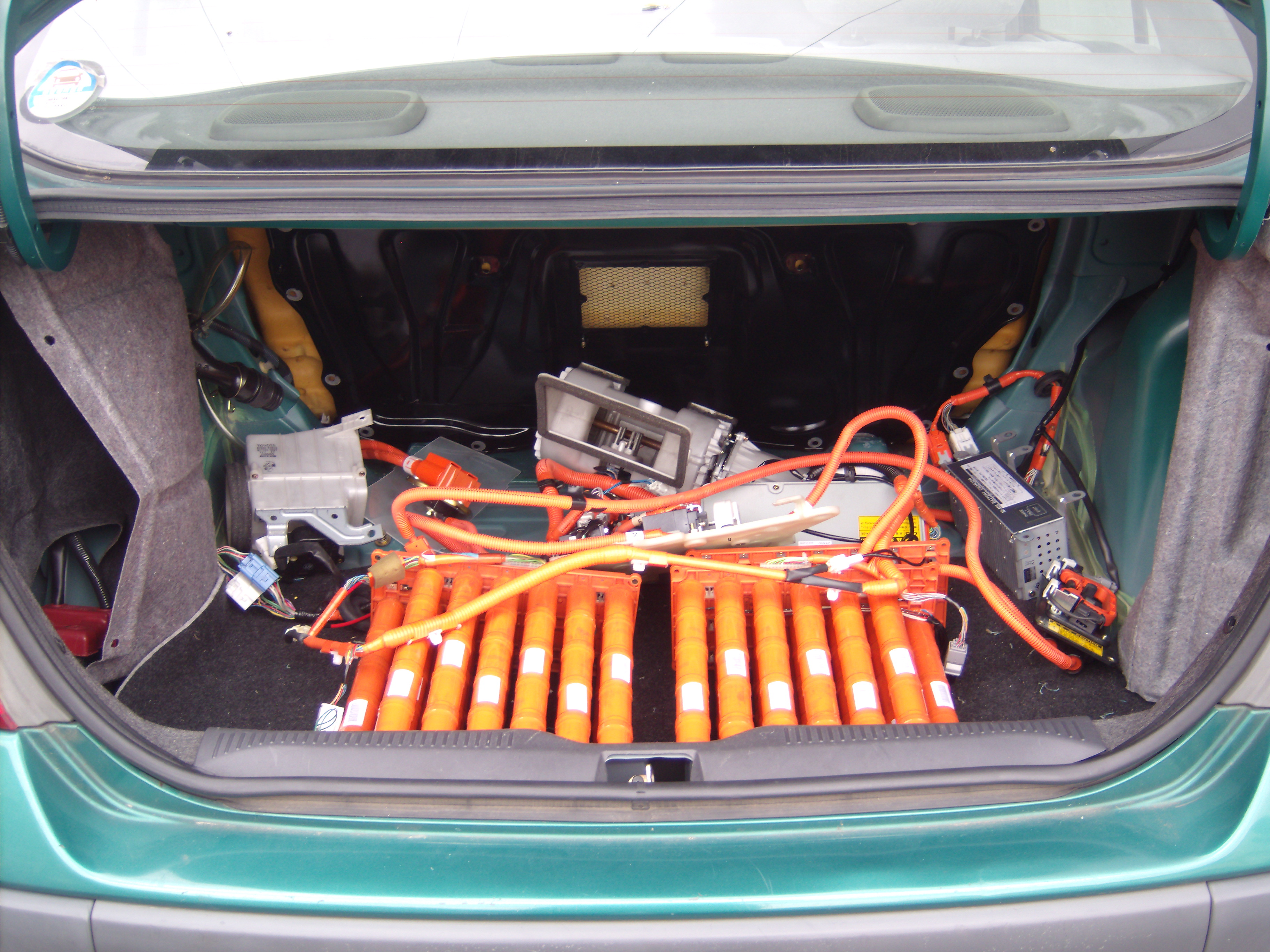
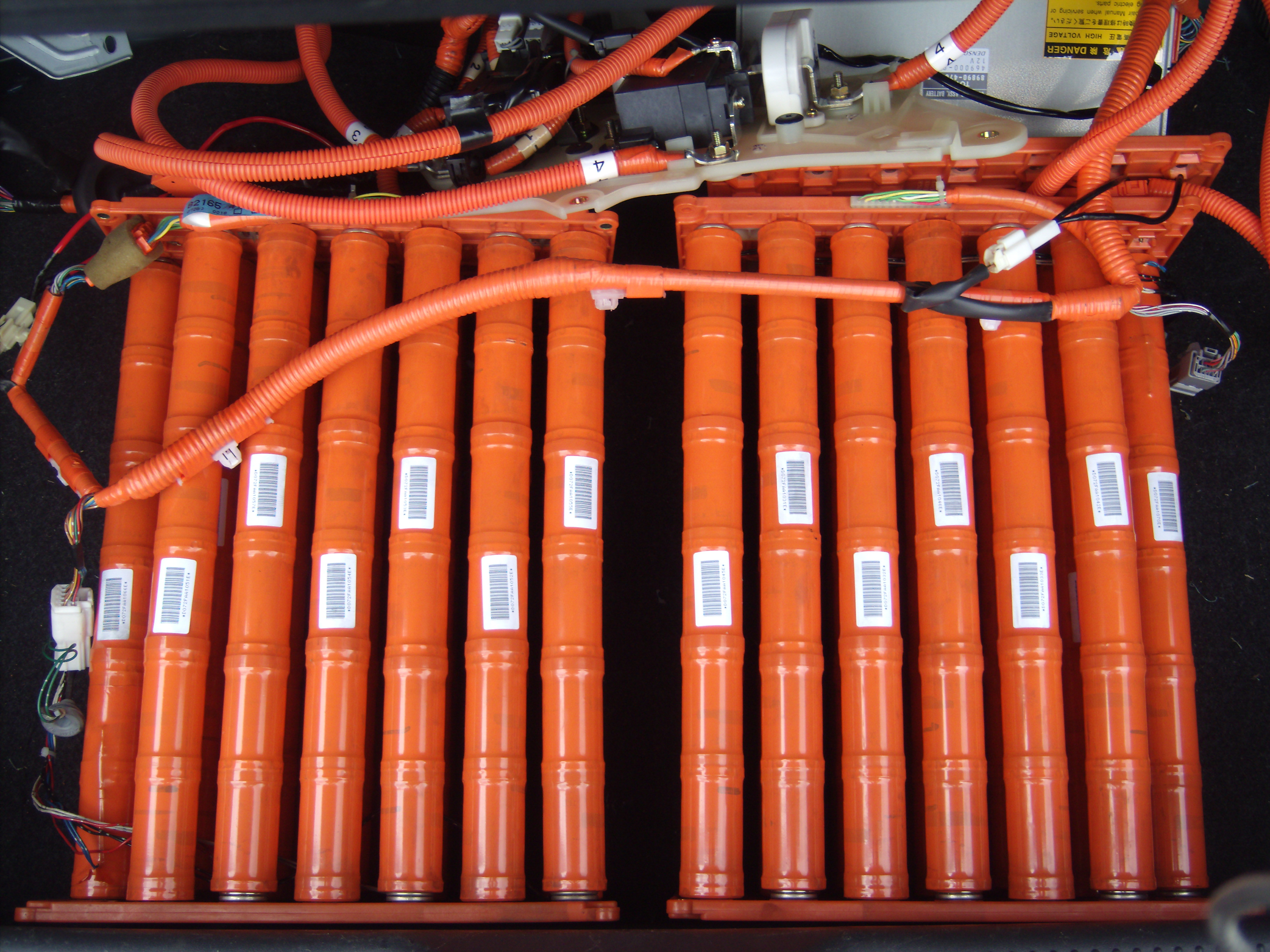
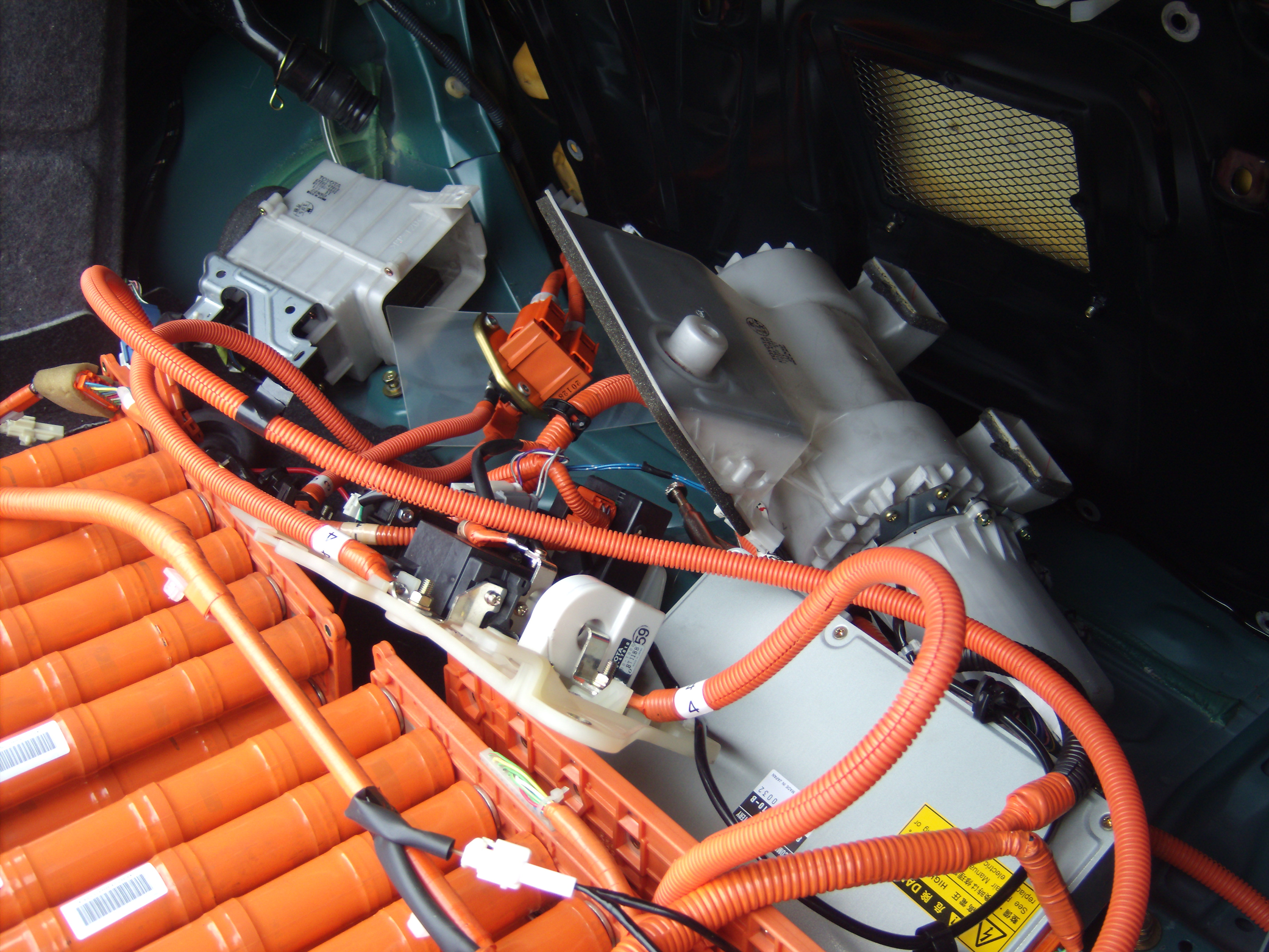
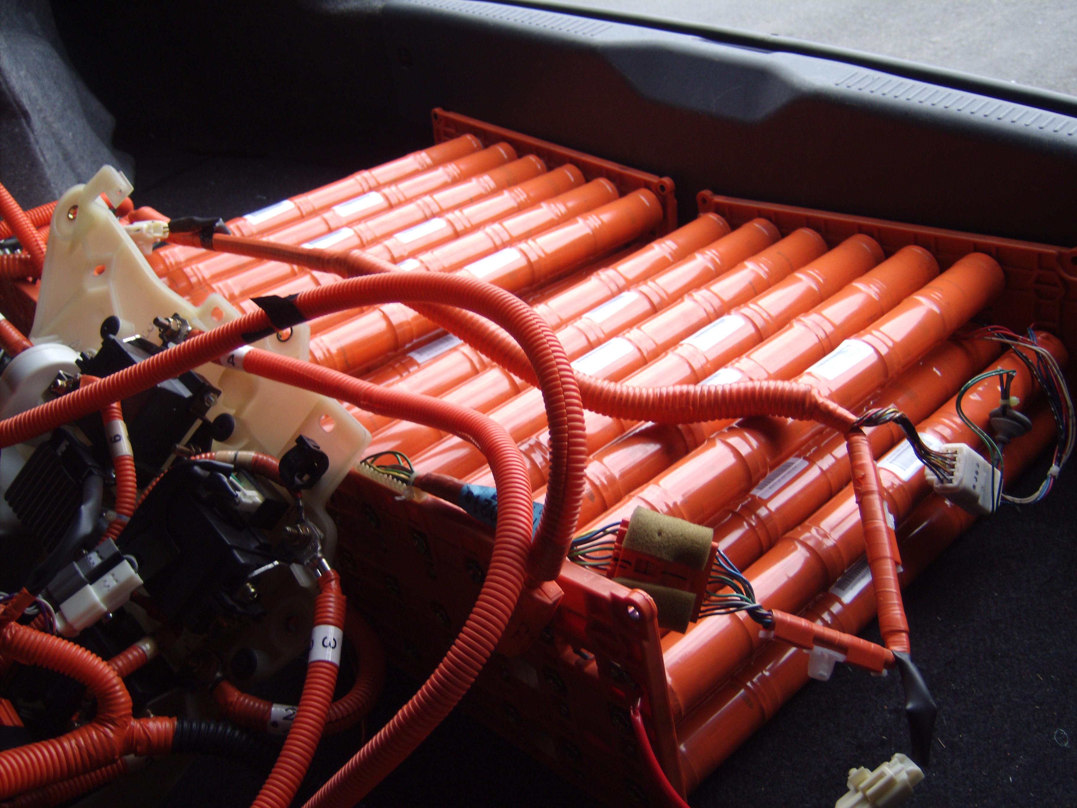
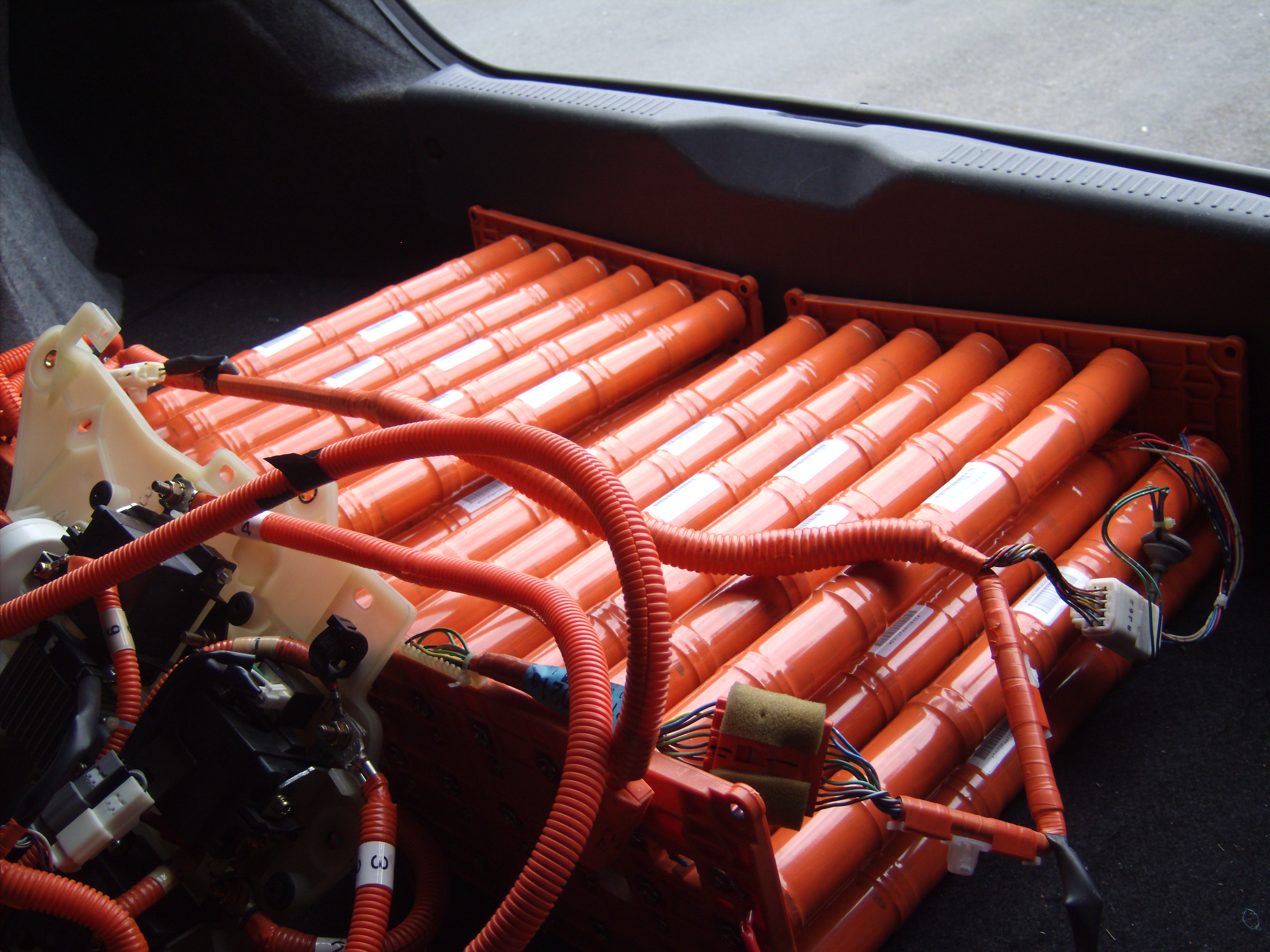
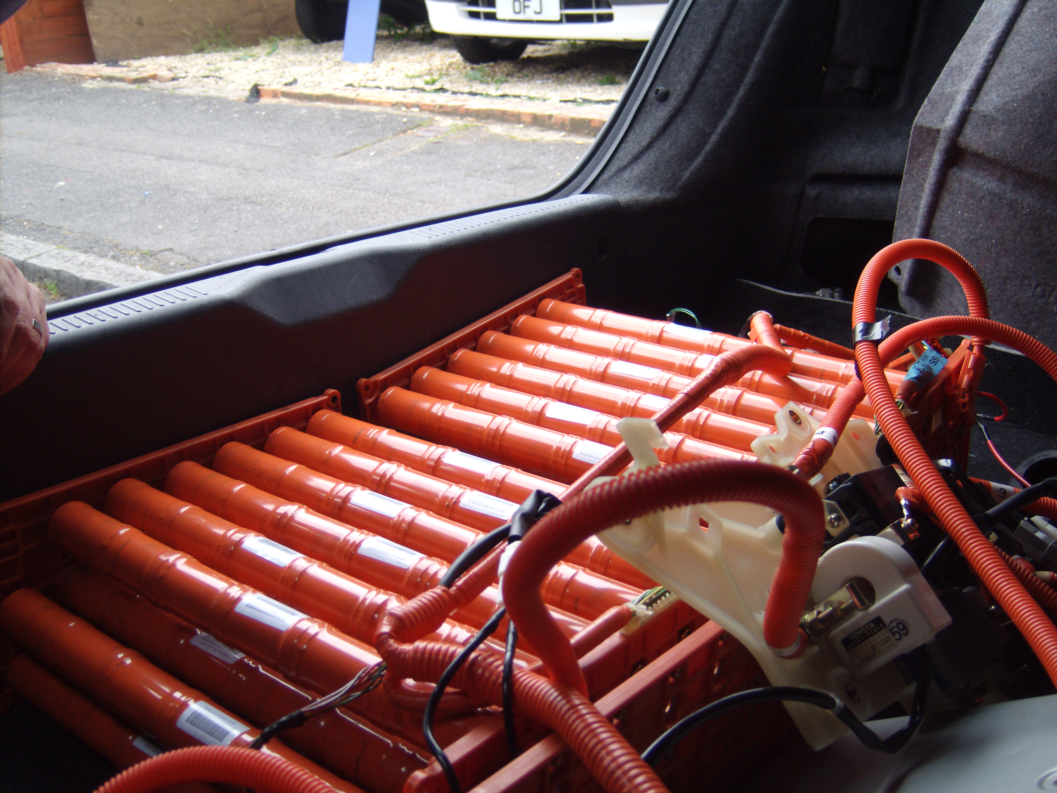
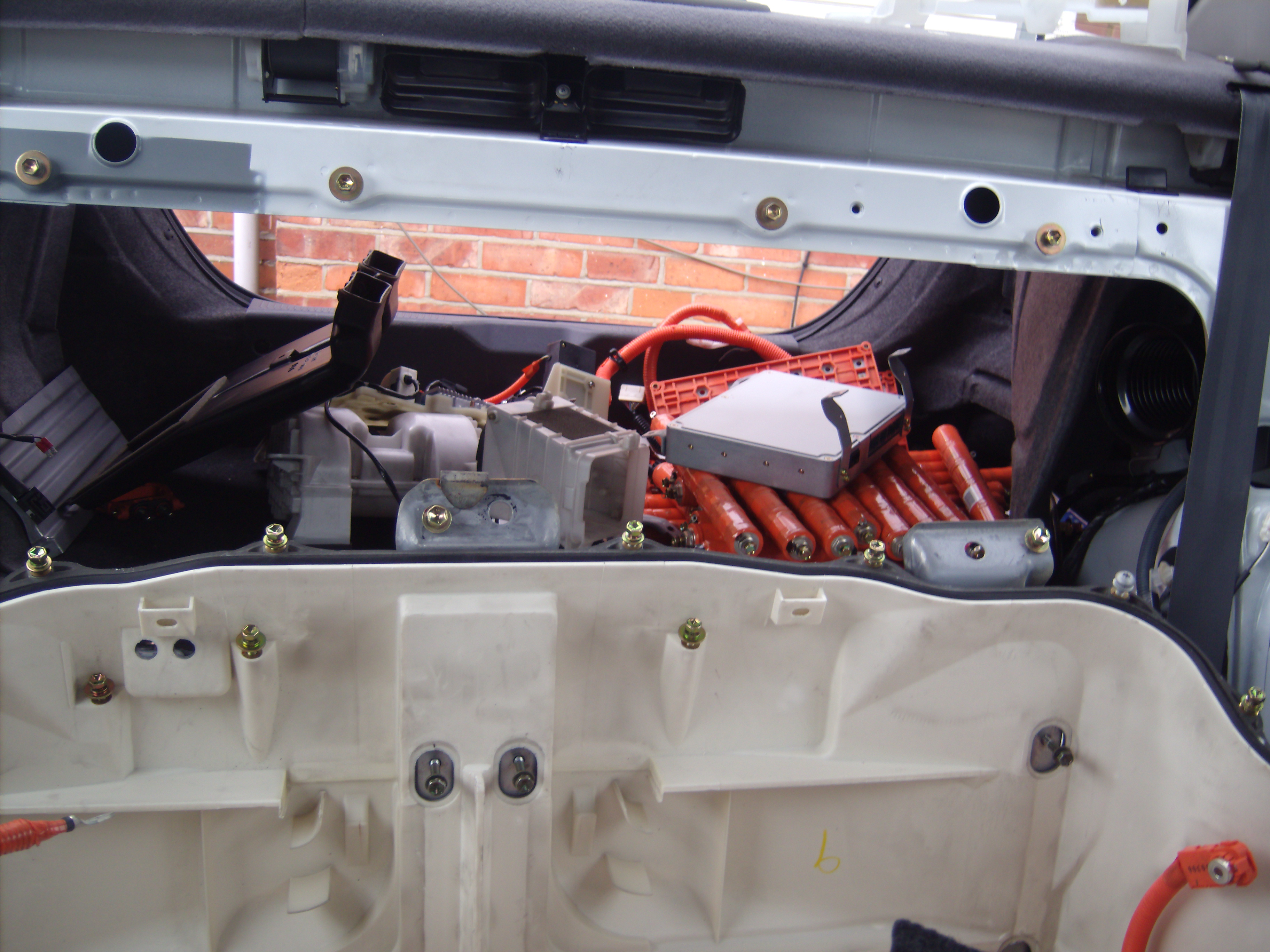
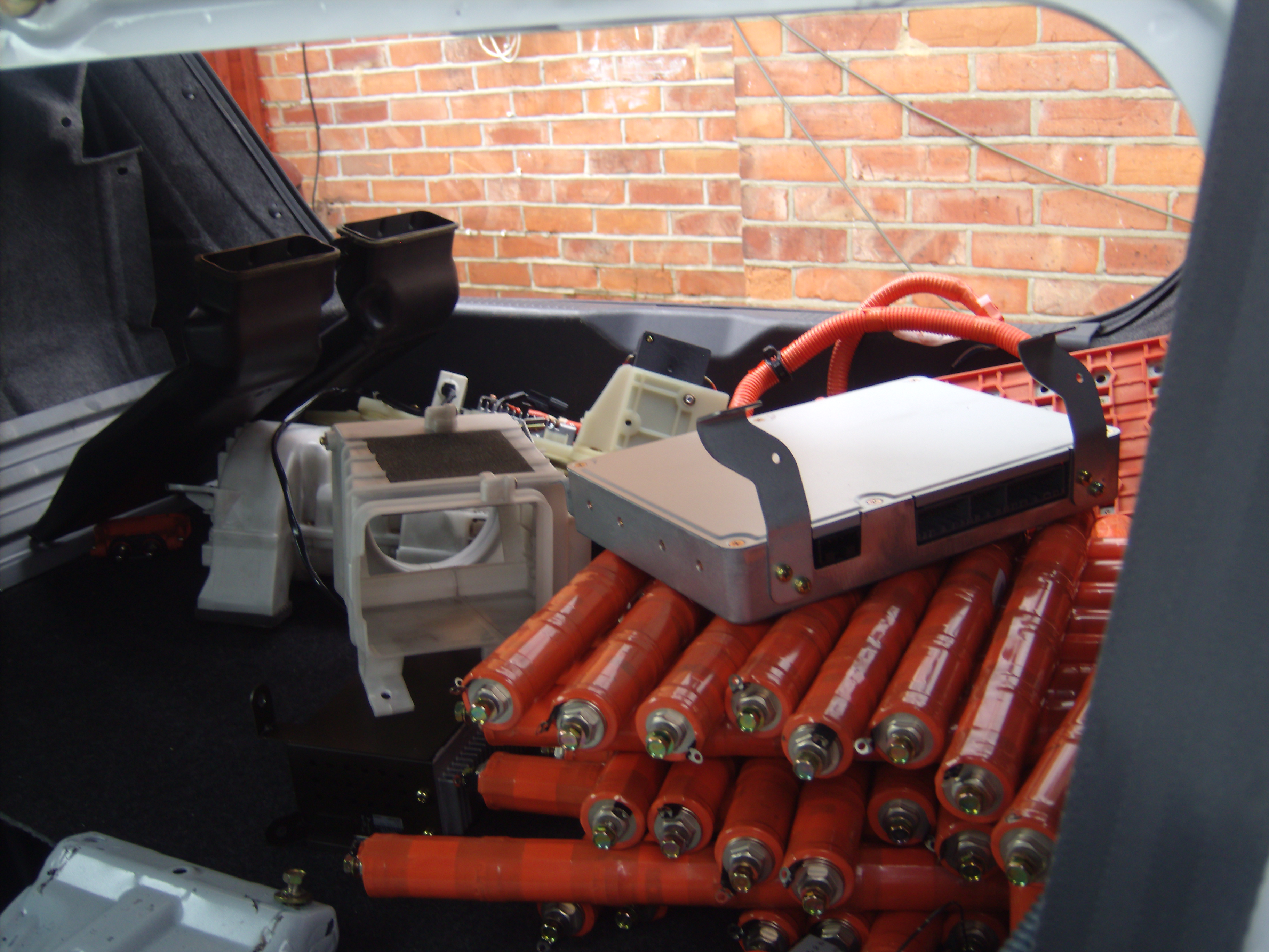
The HV batteries
Green Prius after HV battery casings were stripped away and reconnected.
This is still connected and powering the car normally.
The casings were removed to allow me to experiment with the battery easily.
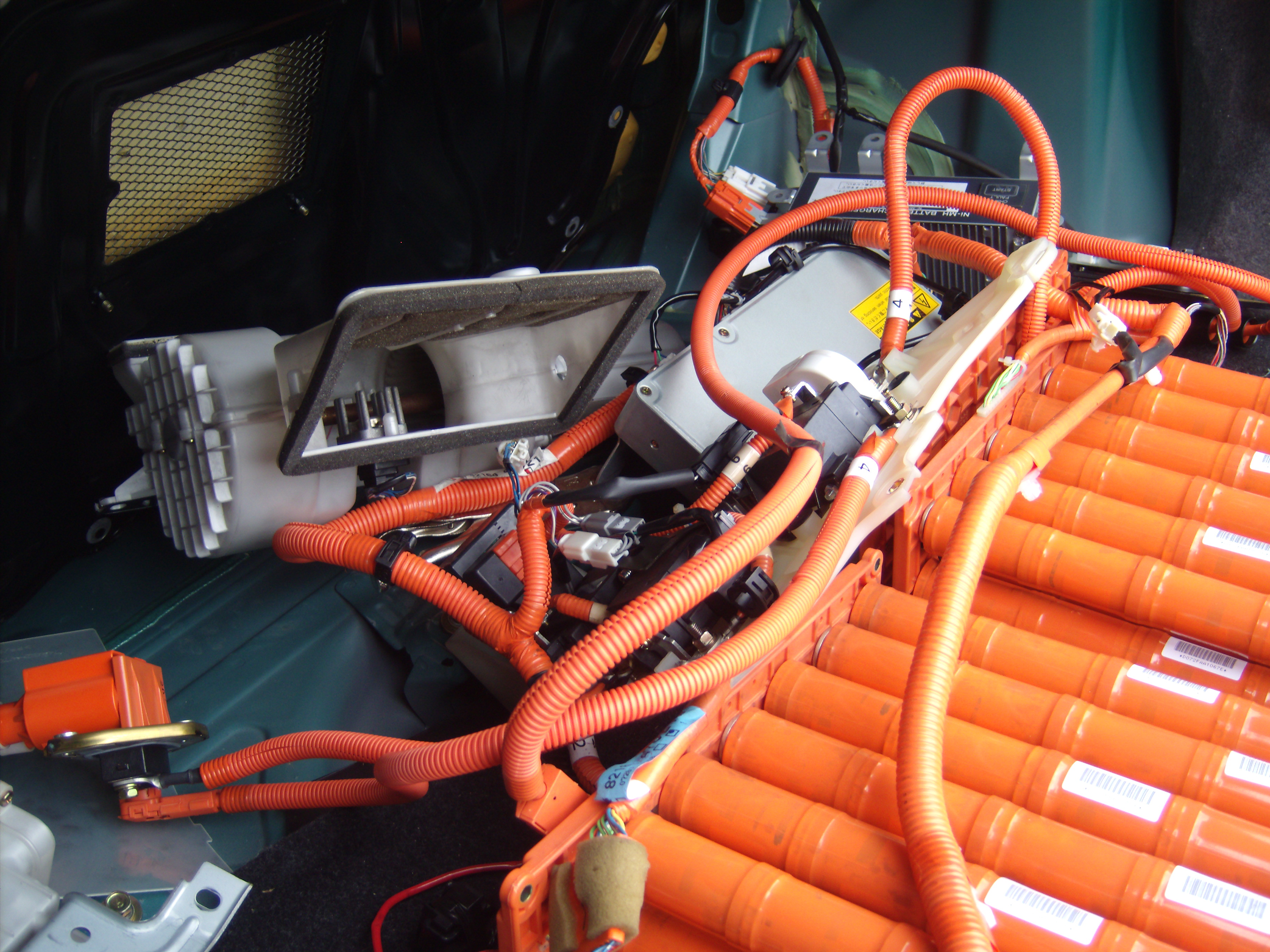
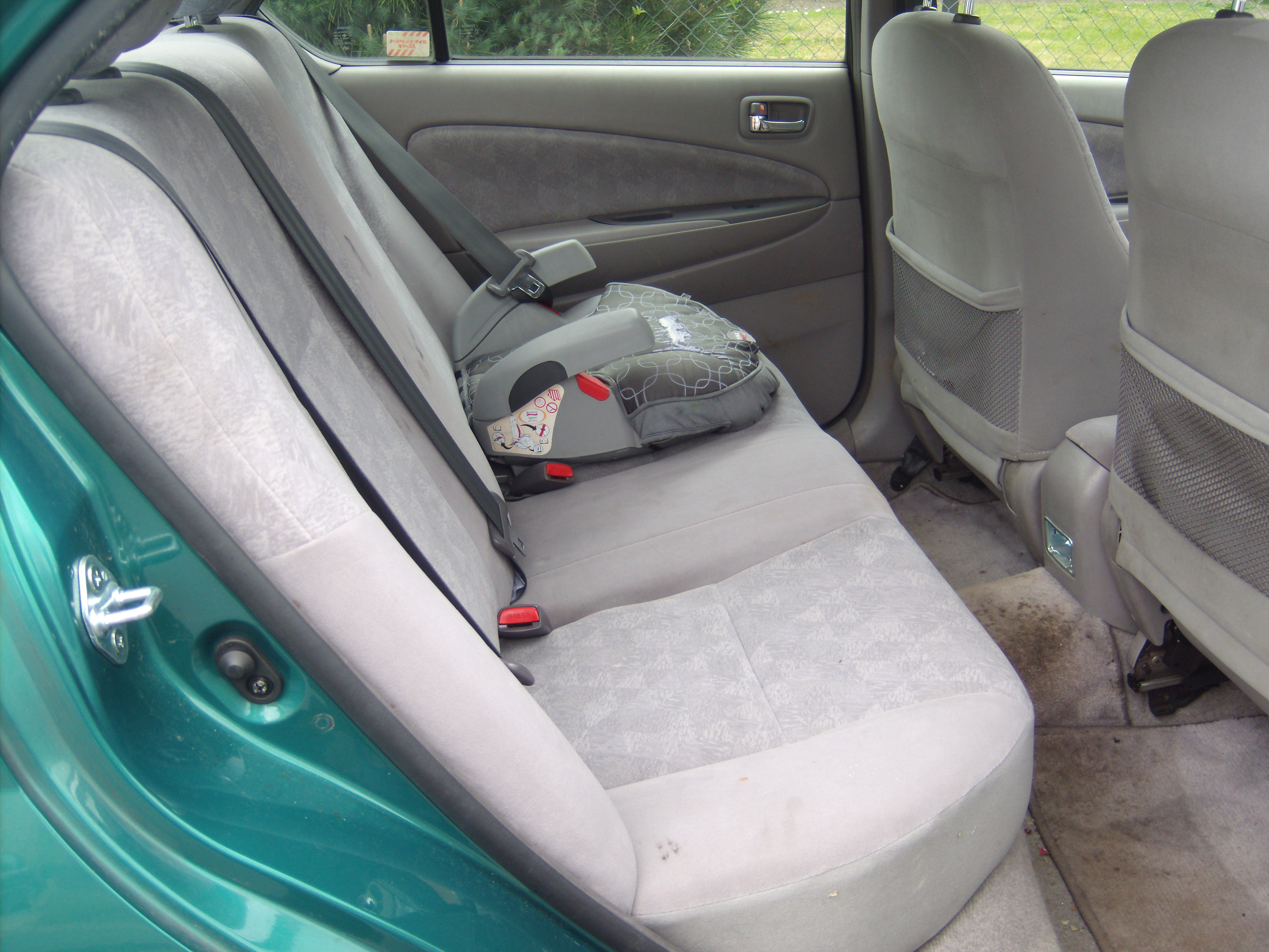
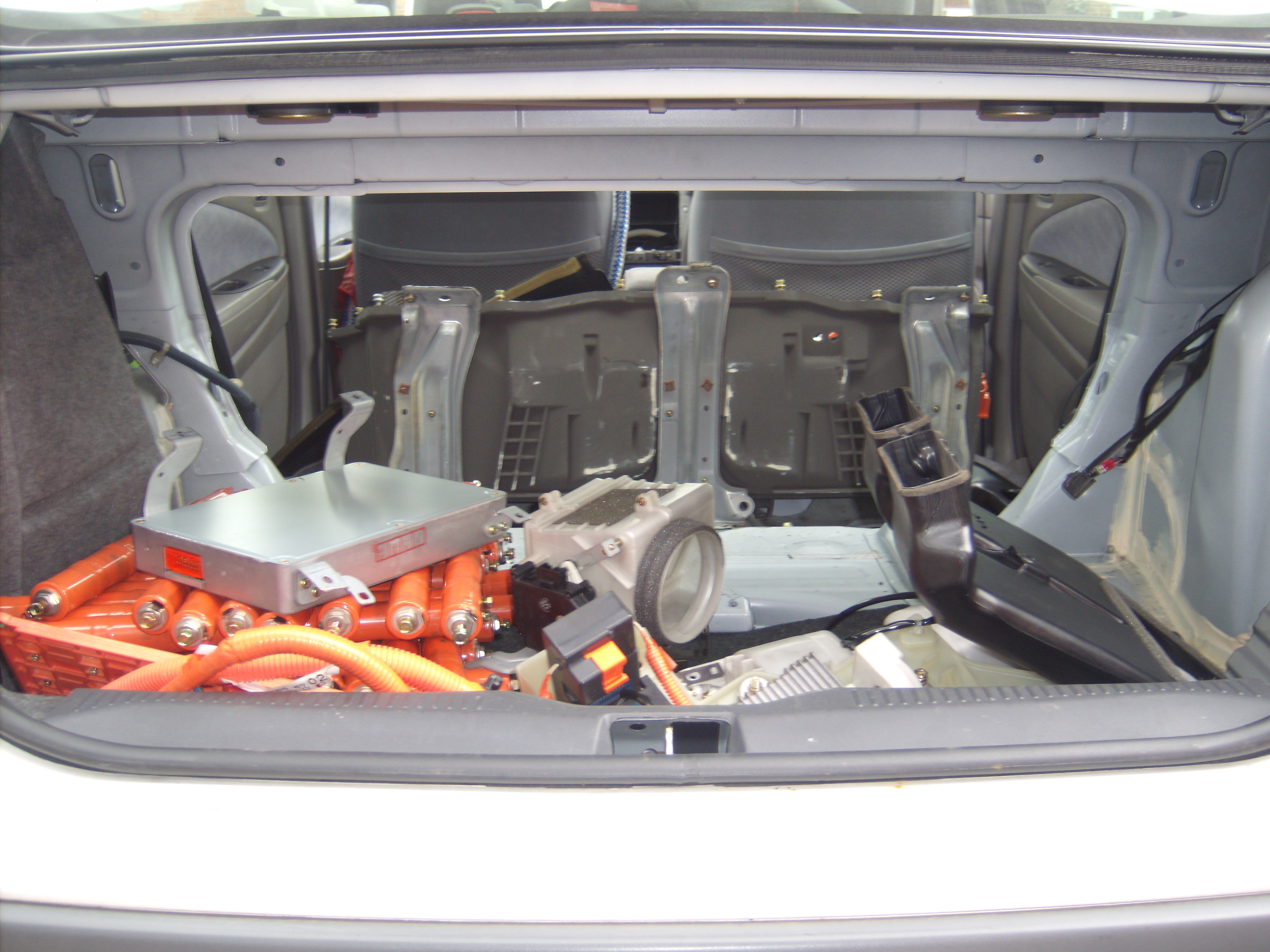
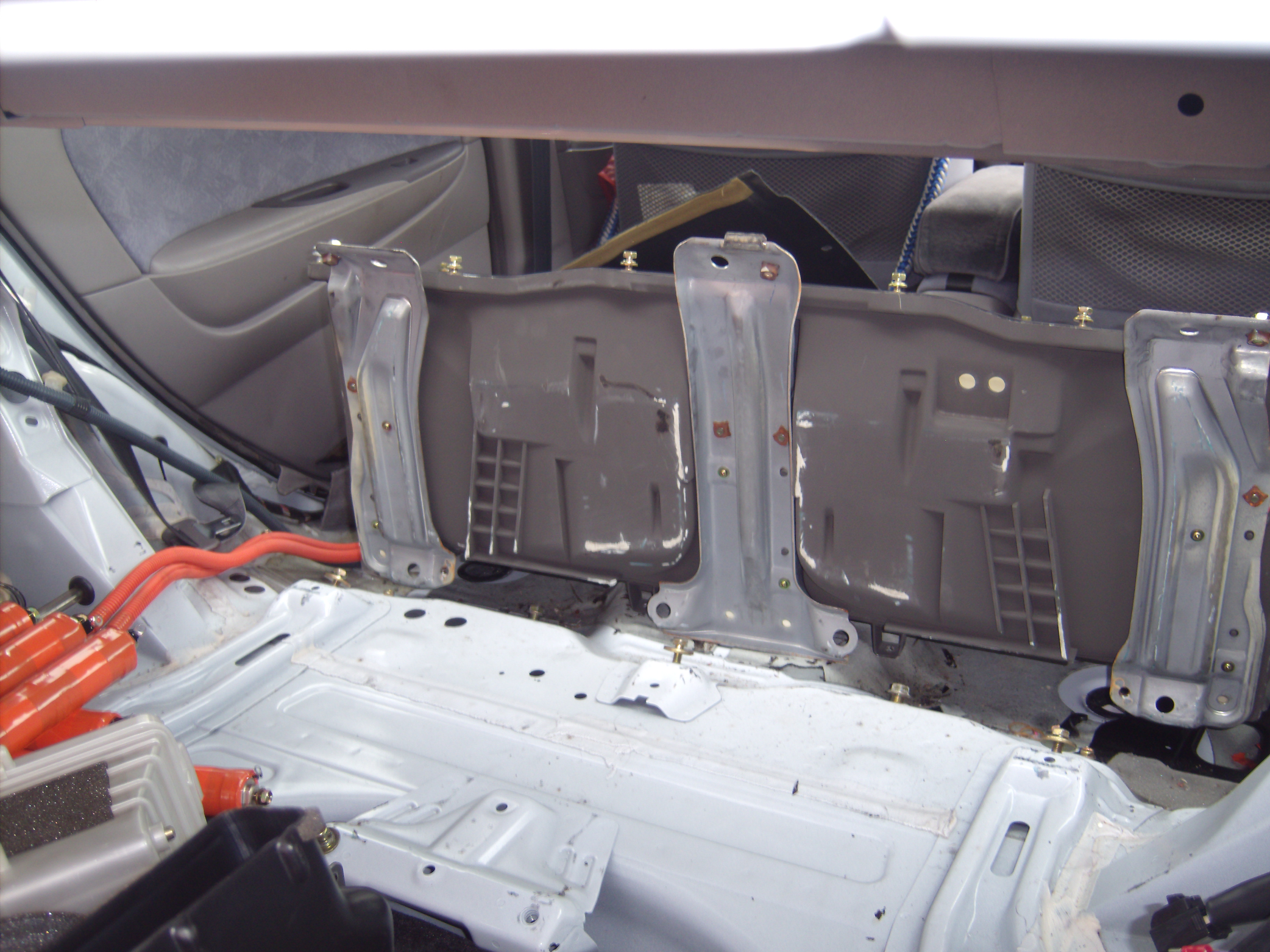
This is the white car showing the battery removed (also the back seats) and dismantled.
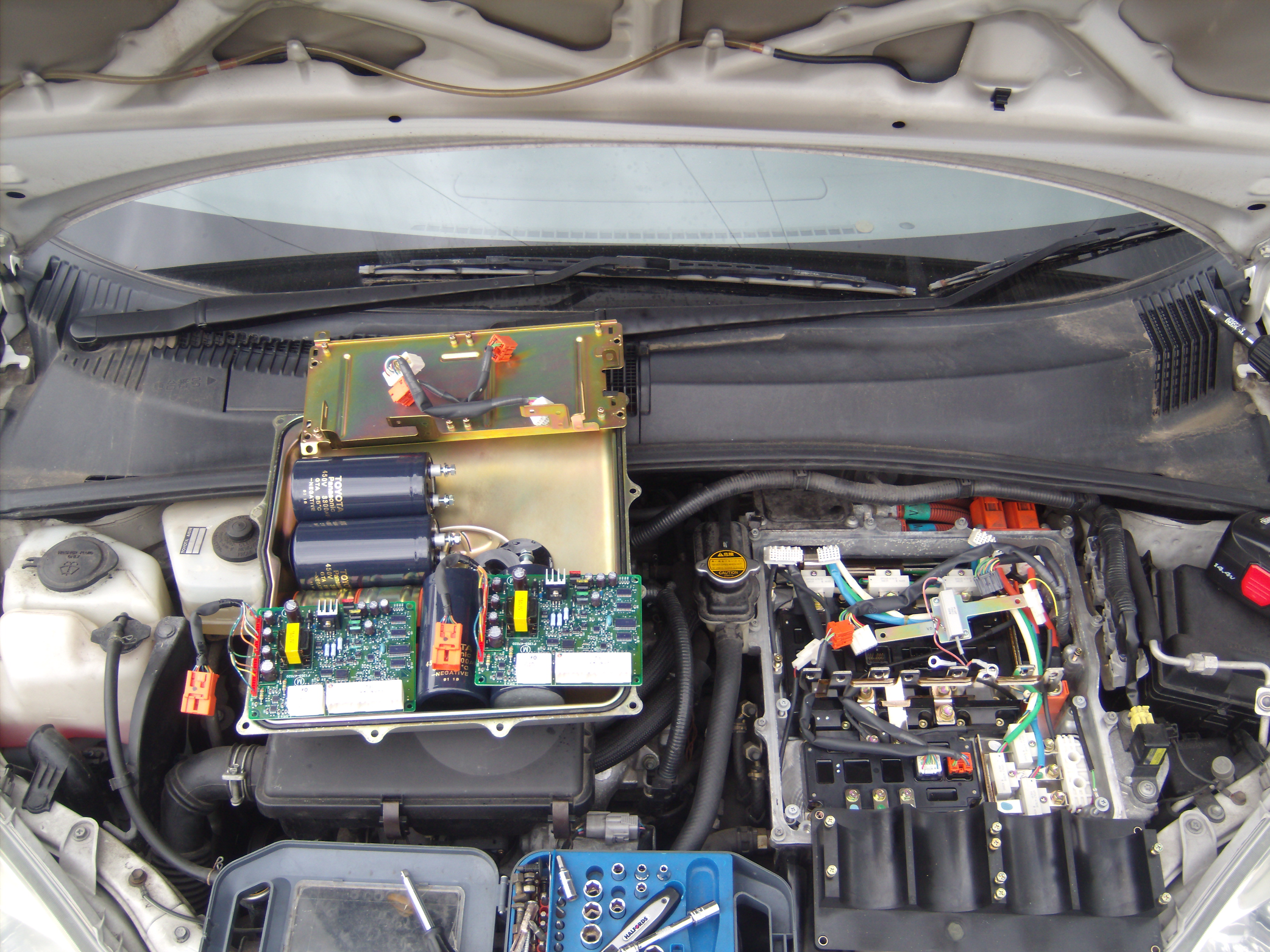
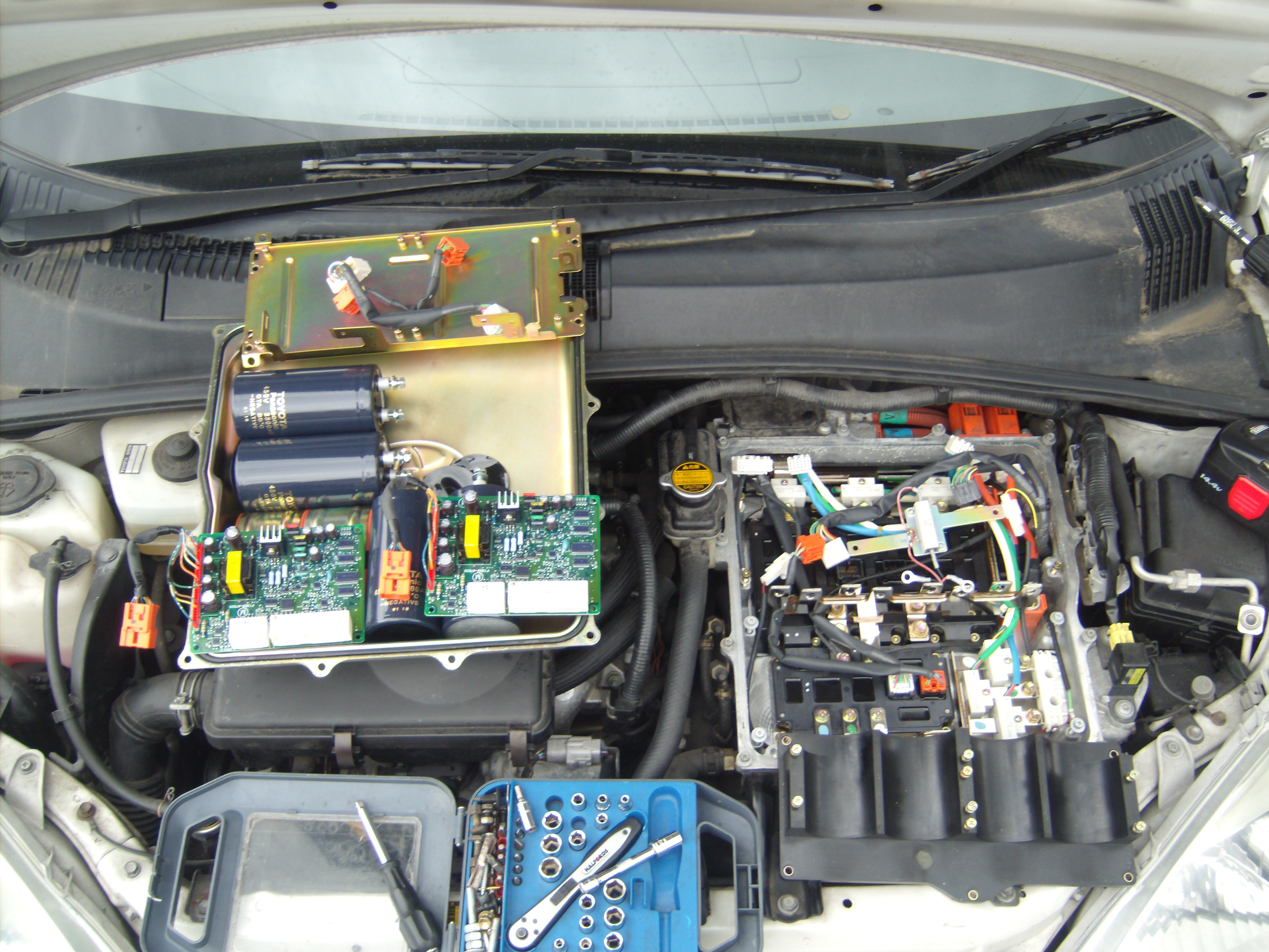
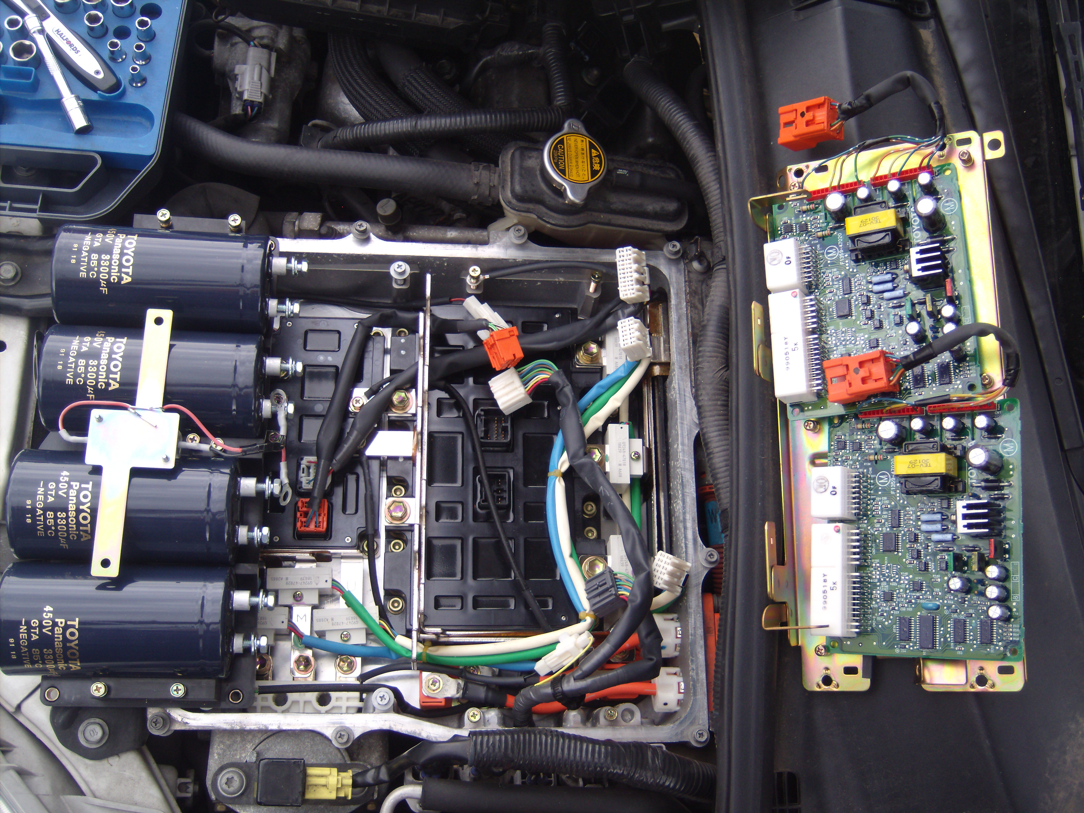
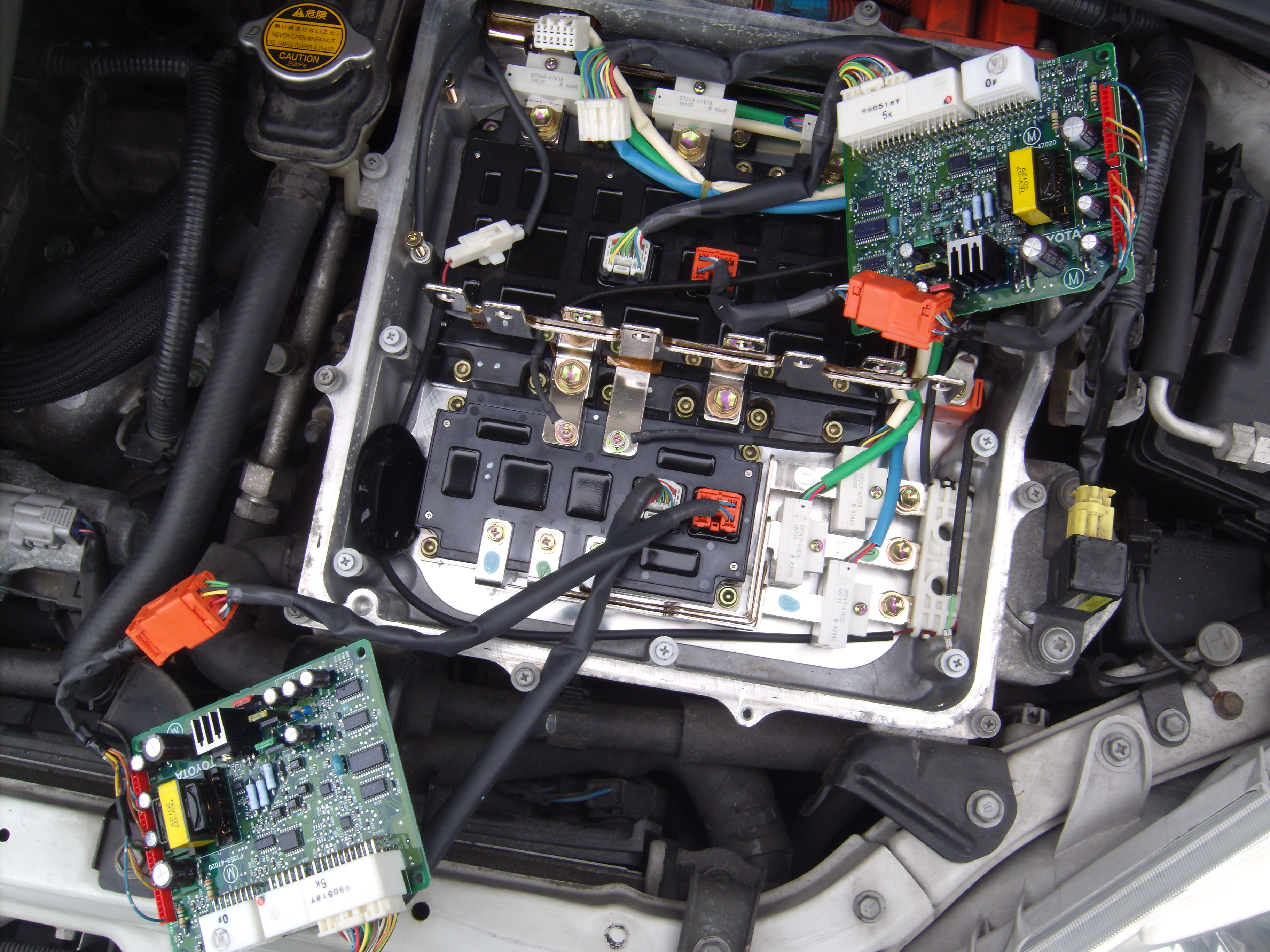
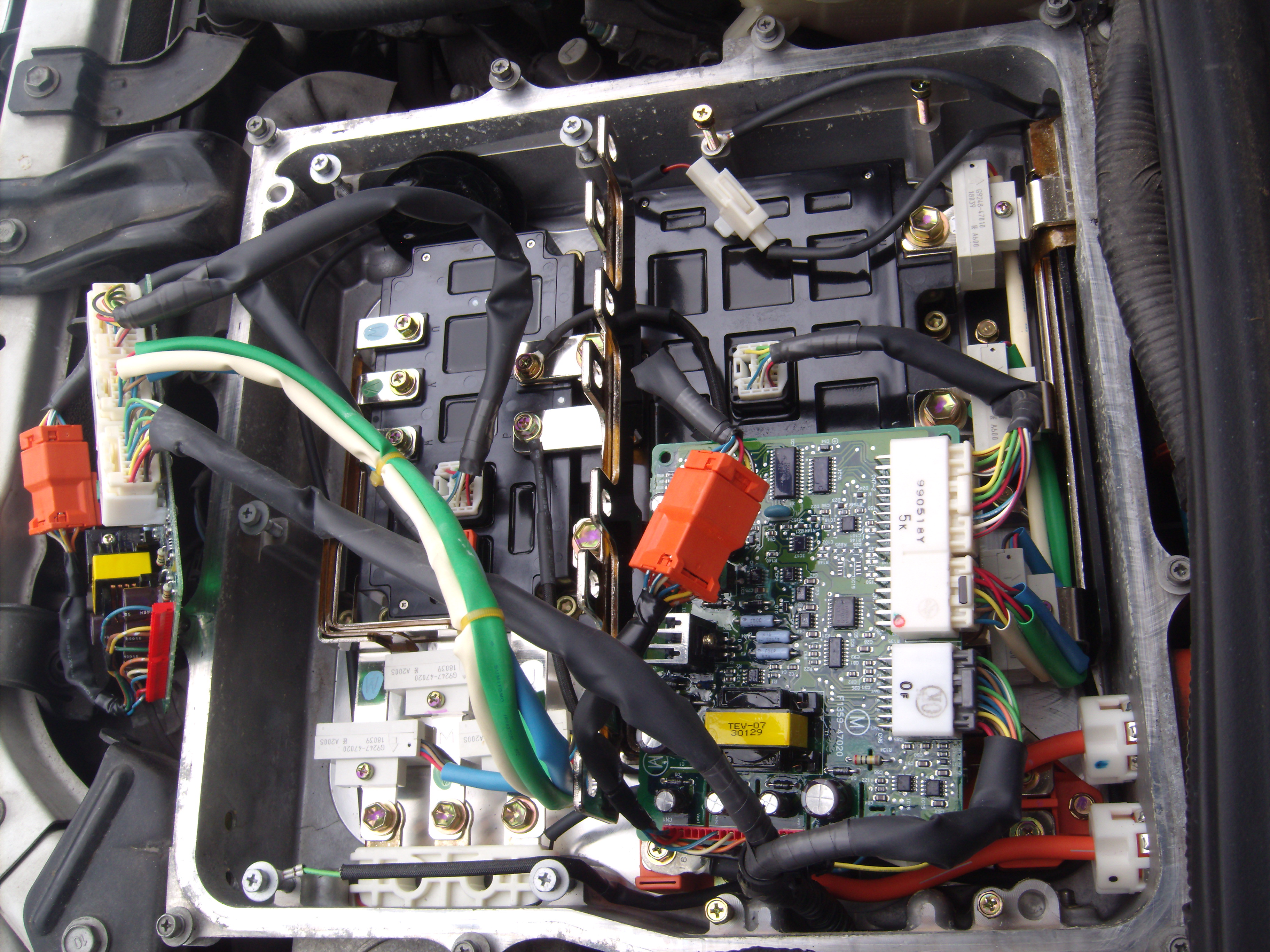
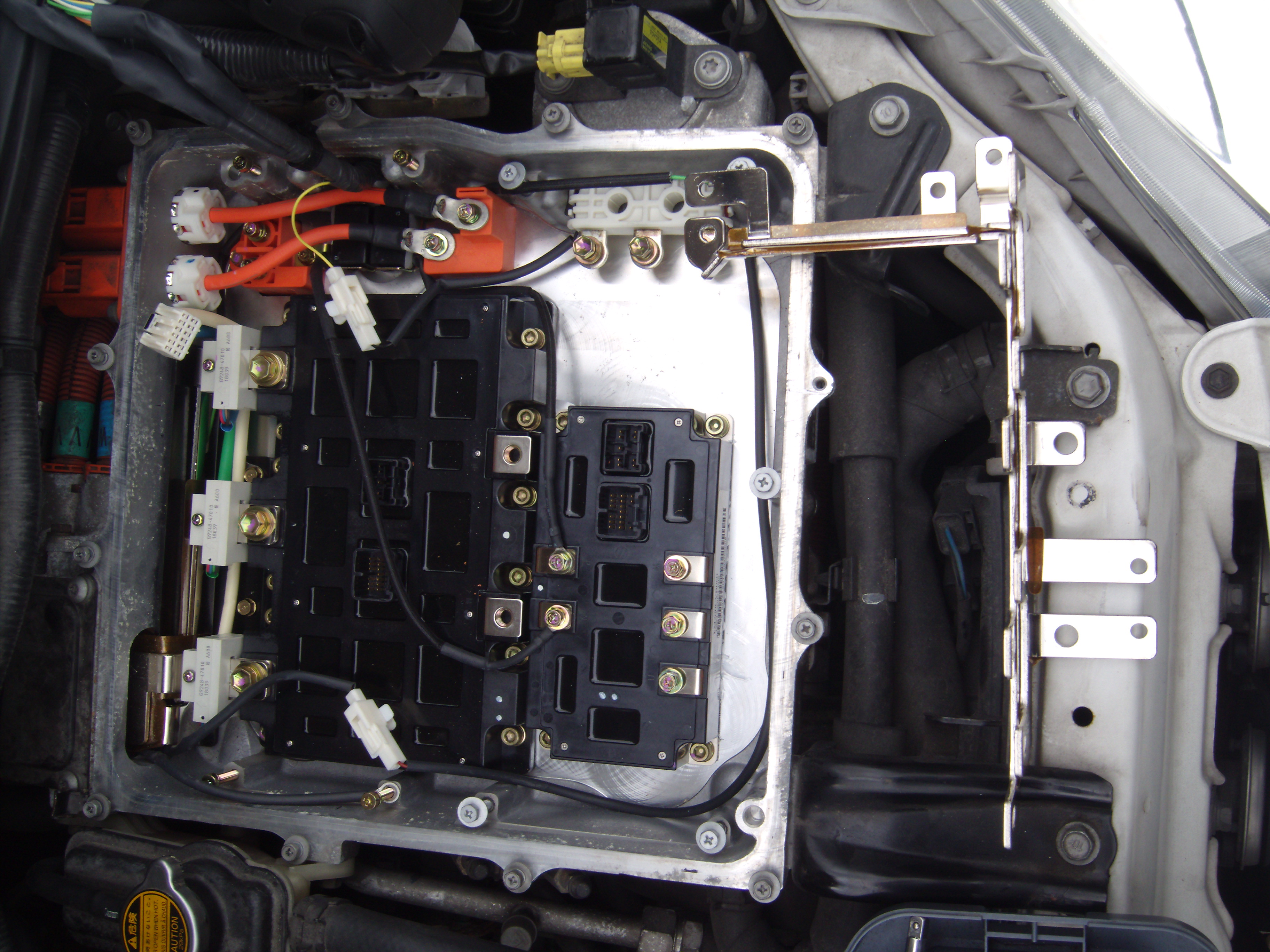
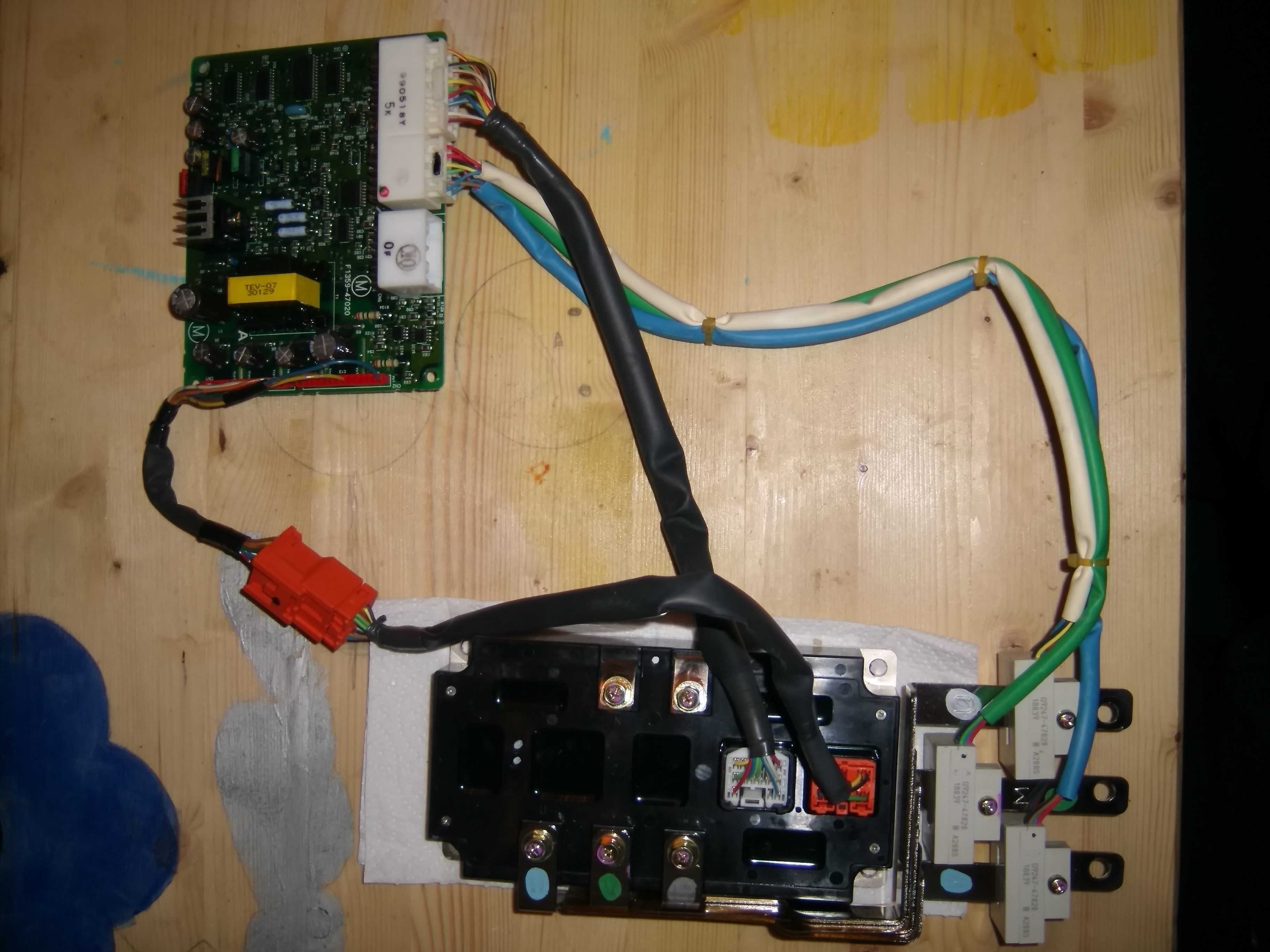
The inverter
This is the white car's controller being dismantled
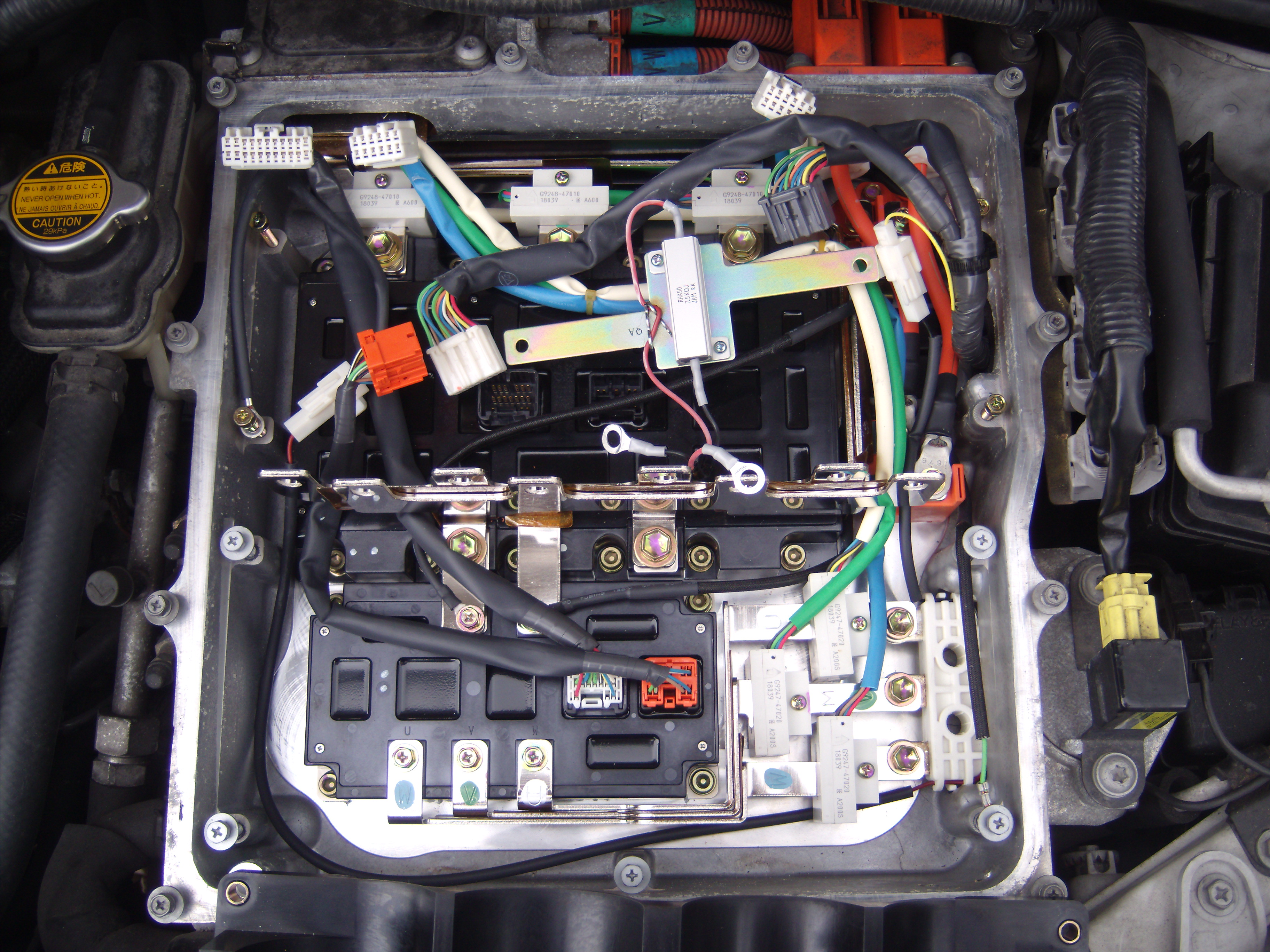
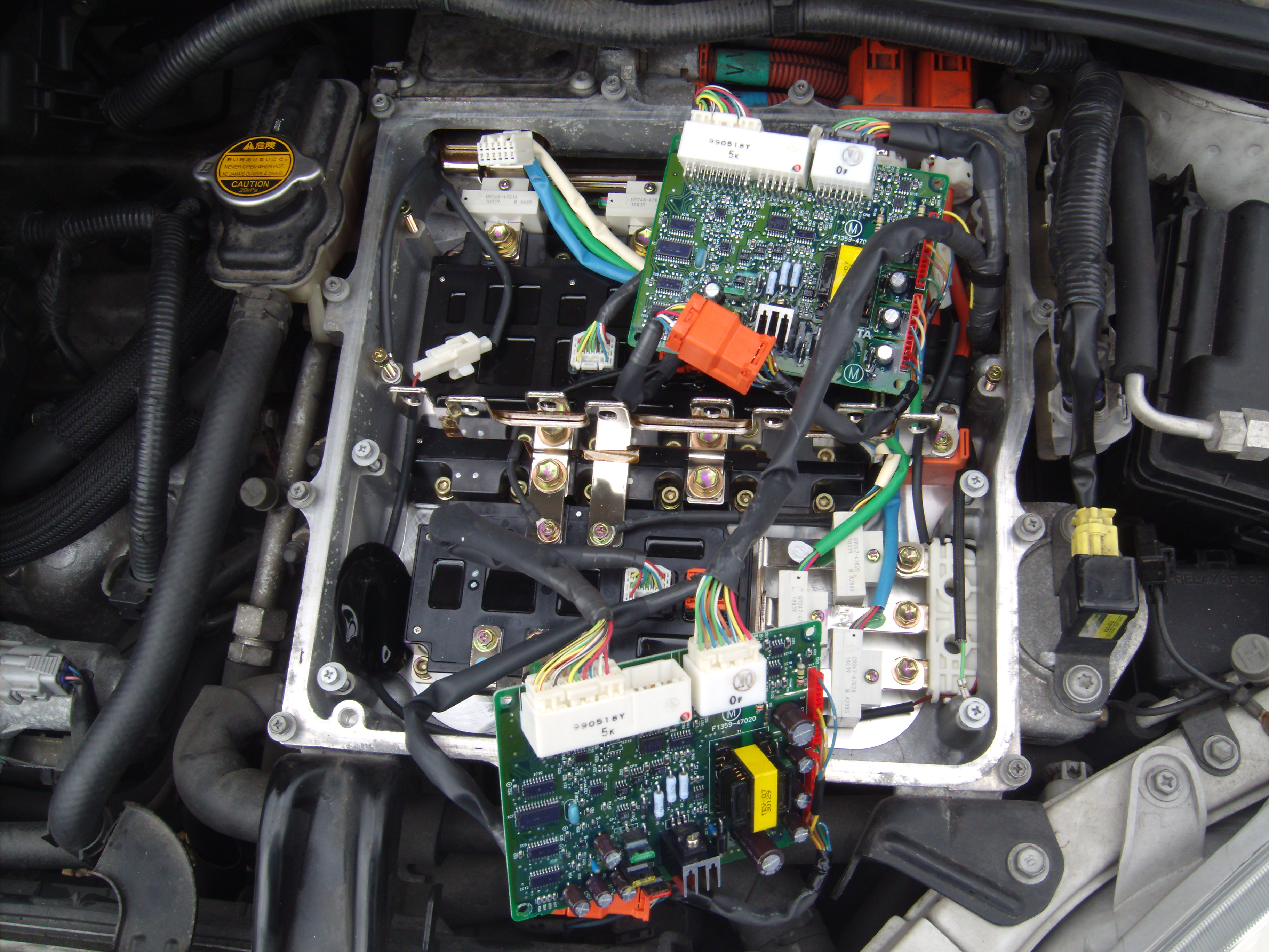
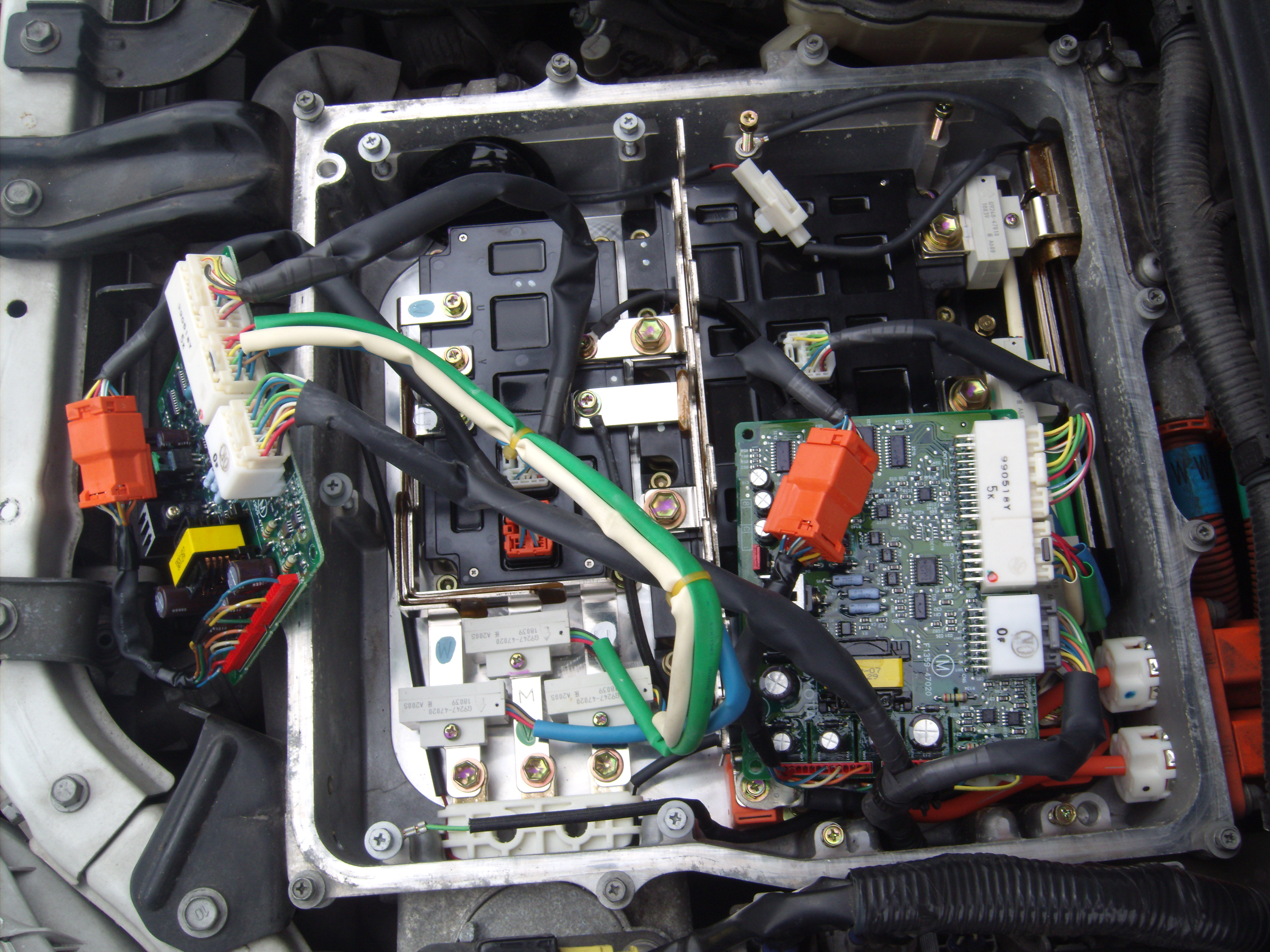
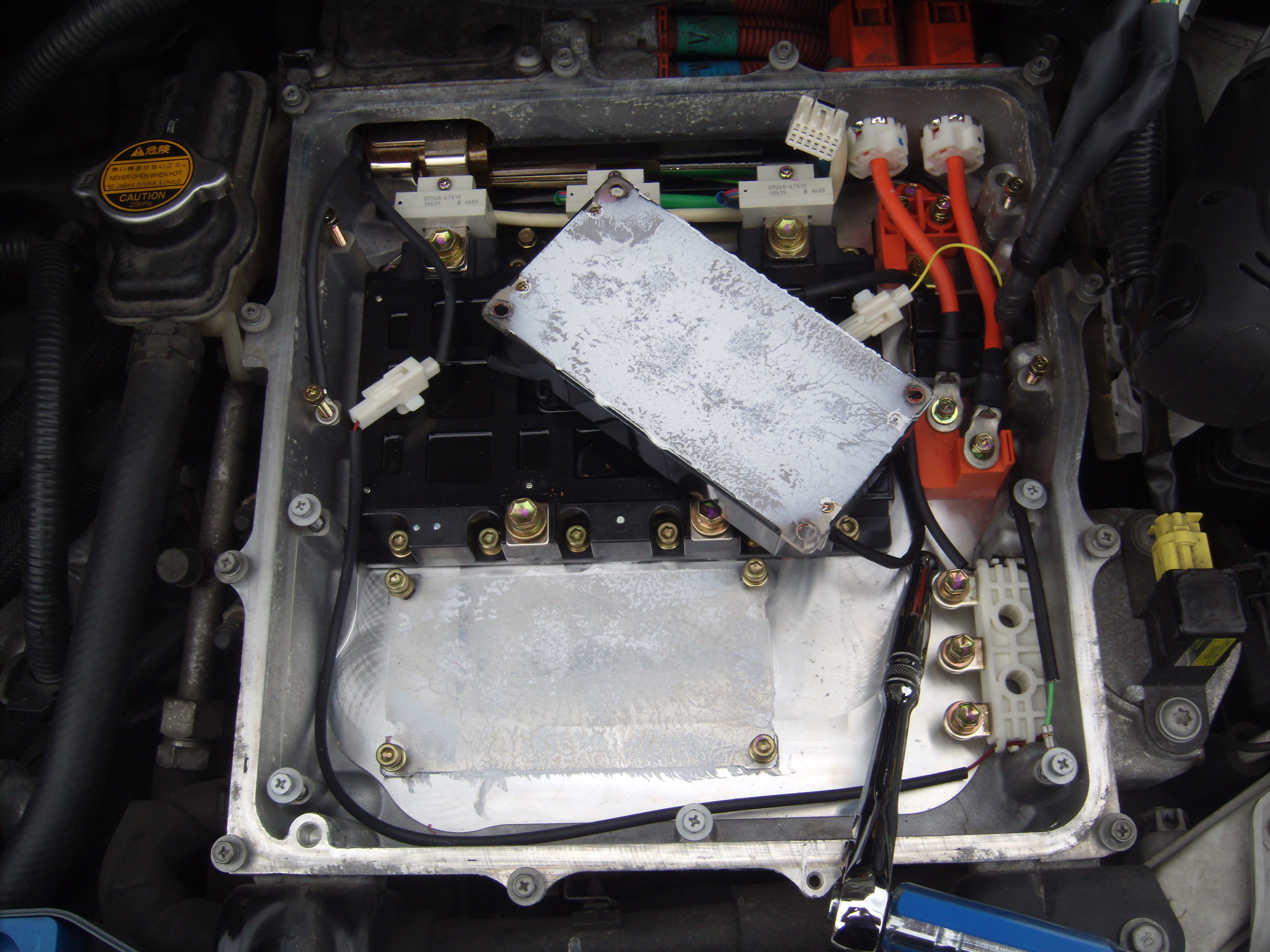
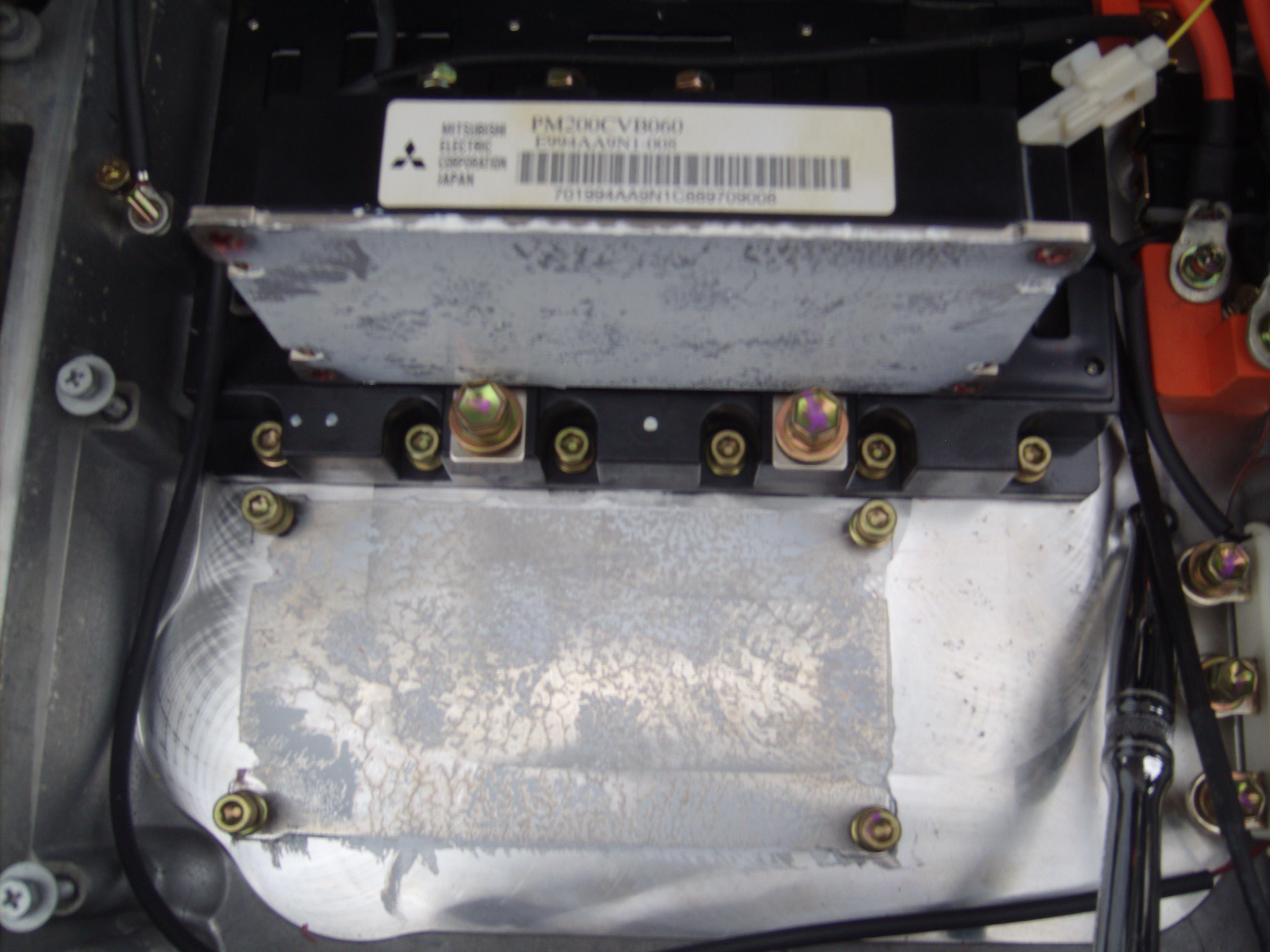
The IGBT block
The plan is to create a new controller for this Gen 1 Prius to make this an EV only car.
The motor(s) will need to be powered from this controller.
Since the expensive bits are already part of the car (motor, transmission, IGBTs, etc), it makes great sense to integrate the new controller into these parts.
The generator (MG1) IGBT block is a PM200CVB060.
The motor (MG2) uses a similar IGBT block which is more powerful, but electrically similar enough that either can be used for the new controller.
The driver boards for both IGBT packs actually have the same part number and they were swapped over on the green car and tested to make sure.
The plan is to use MG2 since this is geared directly to the differential and not through the CVT as MG1.
This will also be powerful enough for even motorway speeds, so no need to bother with MG1.
What this means is that experimentation can be done with MG1 and it's IGBT pack to debug the controller and electronics.
We can then use the fully debugged kit on MG2 and it's IPM.
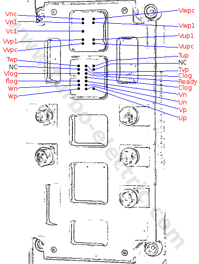
Unfortunately, there isn't a datasheet on the PM200CVB060, but there is for a PM200CVA060, which going to be the same inside but with a different connector arrangement.
Luckily, the guys who made the driver boards put the pin assignments on it too, so it's just a case of following the wires to the pins on the IGBT pack and we complete the picture.
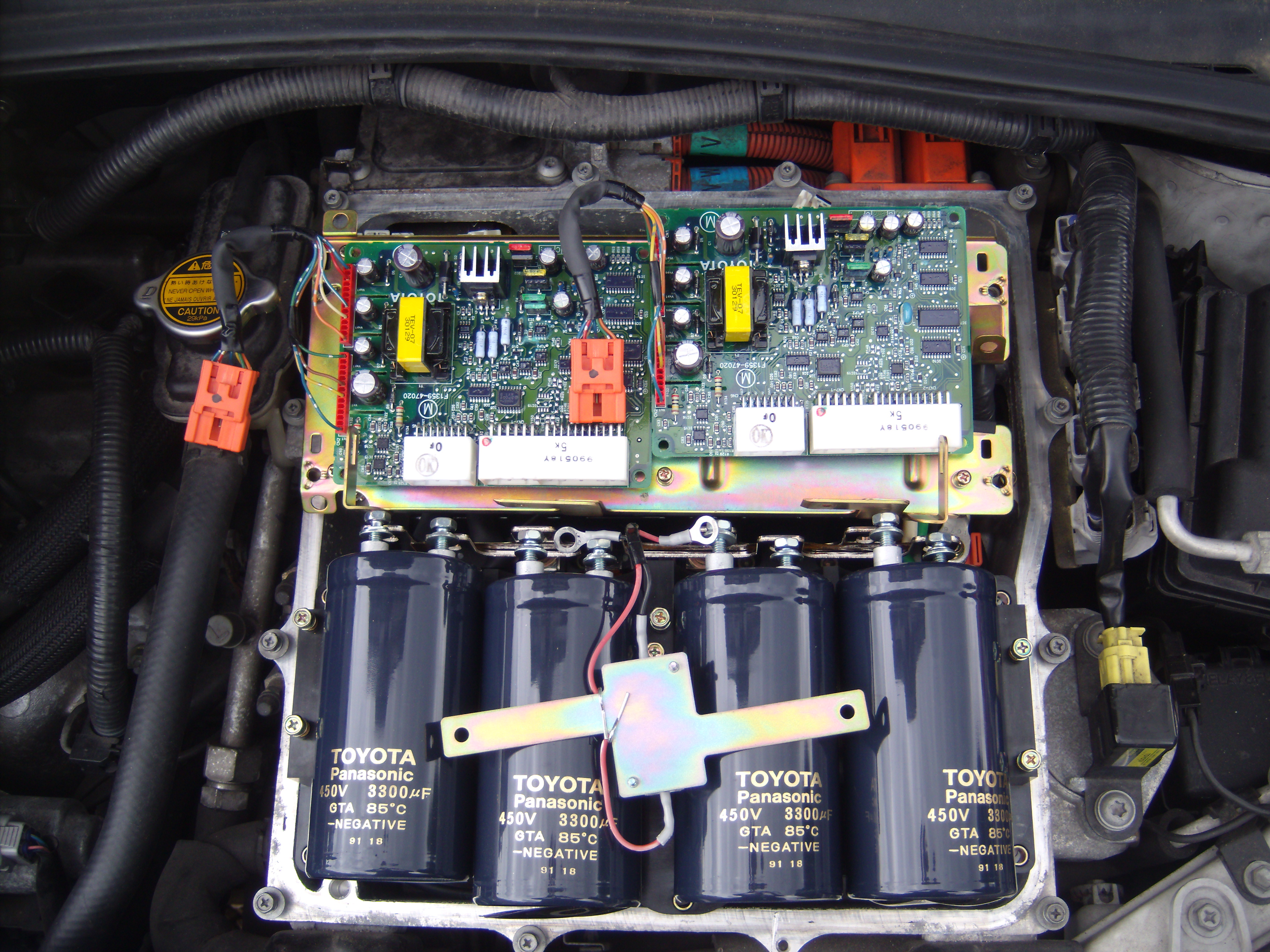
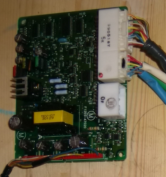
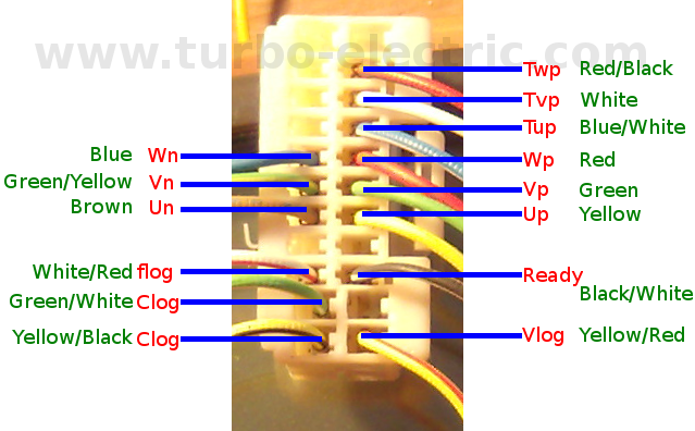
One of a pair of driver boards from a Gen 1 Prius Inverter.
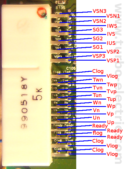
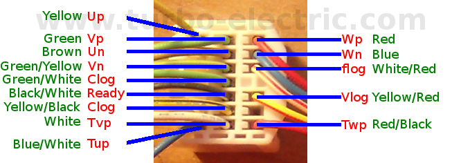
The IGBT connectors on the driver board.
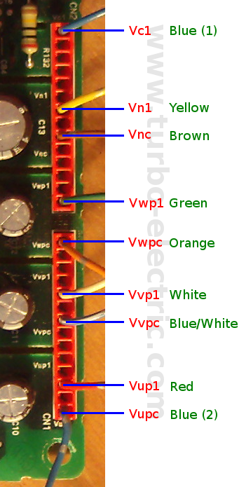
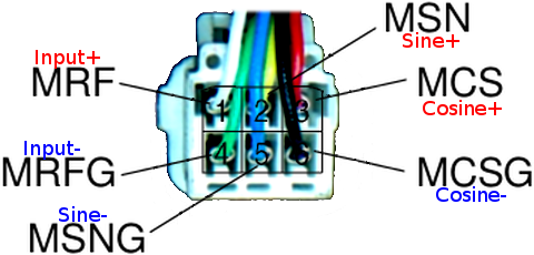
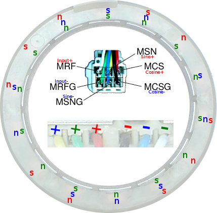
Pinout and wiring of the white connection.
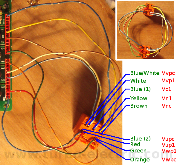
The Orange Plug connectors from the driver board.
The upper-right image is a plug to plug which shows a mirror pin mapping.
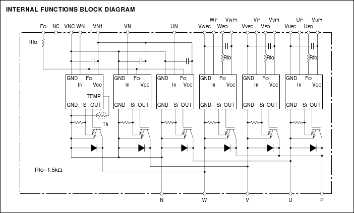
Full Pinout of the PM200CVB060 (previously unreleased)
Full pinout of the PM200CVB060 IGBT Power Inverter Module which controls MG1.
This is the same pinout for the IPM, which controls the MG2.
PM200CVA060 Block Diagram.
This can be now used for the PM200CVB060 also.
Prius IPM motor control test done by jddcircuit.
Apparently jddcircuit has successfully used the original Prius resolver and field drivers to power a car.
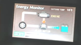
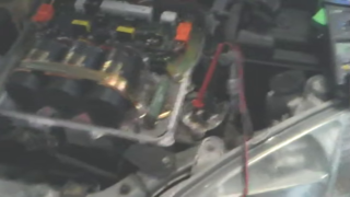
Prius Generator
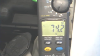
Prius generator during a charge:
The set up.
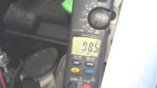
We are metering across a single phase so for the rectified output (RMS) you should multiply by root of 3.
Highest observed during test:
Lowest observed (just before engine shut off):
Presumably the 74.2v will be at 1,000 rpm (the minimum of the engine before shut off)
So we would get 100.3 x SQR(3) = 173.7v and 74.2 x SQR(3) = 129v
The lowest (1,000 RPM) engine speed would be 3,611 RPM at the generator.
We can go up to 1,800 RPM engine speed (6,500 generator) which should give us 130v * 1,800 / 1,000 = 232v
Current at 15kW is 15000 / 232 = 64.7A.
So we should be able to get over 200vDC and over 50A from MG1.
Probably spec up diodes for the trailer generator rectifier at 100A.
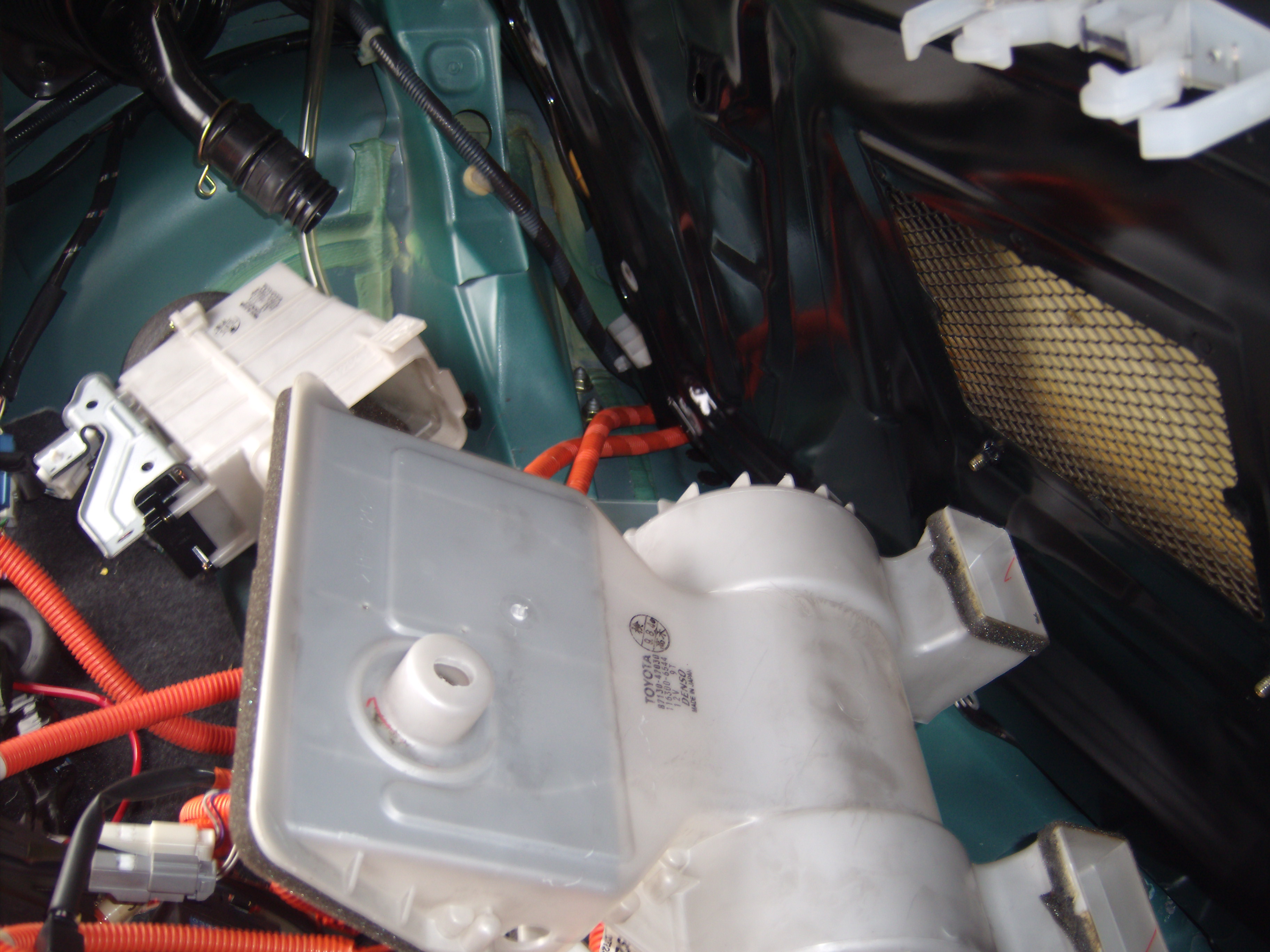
Motor Position Sensing
In order to control the Prius motor we need to access the position sensors.
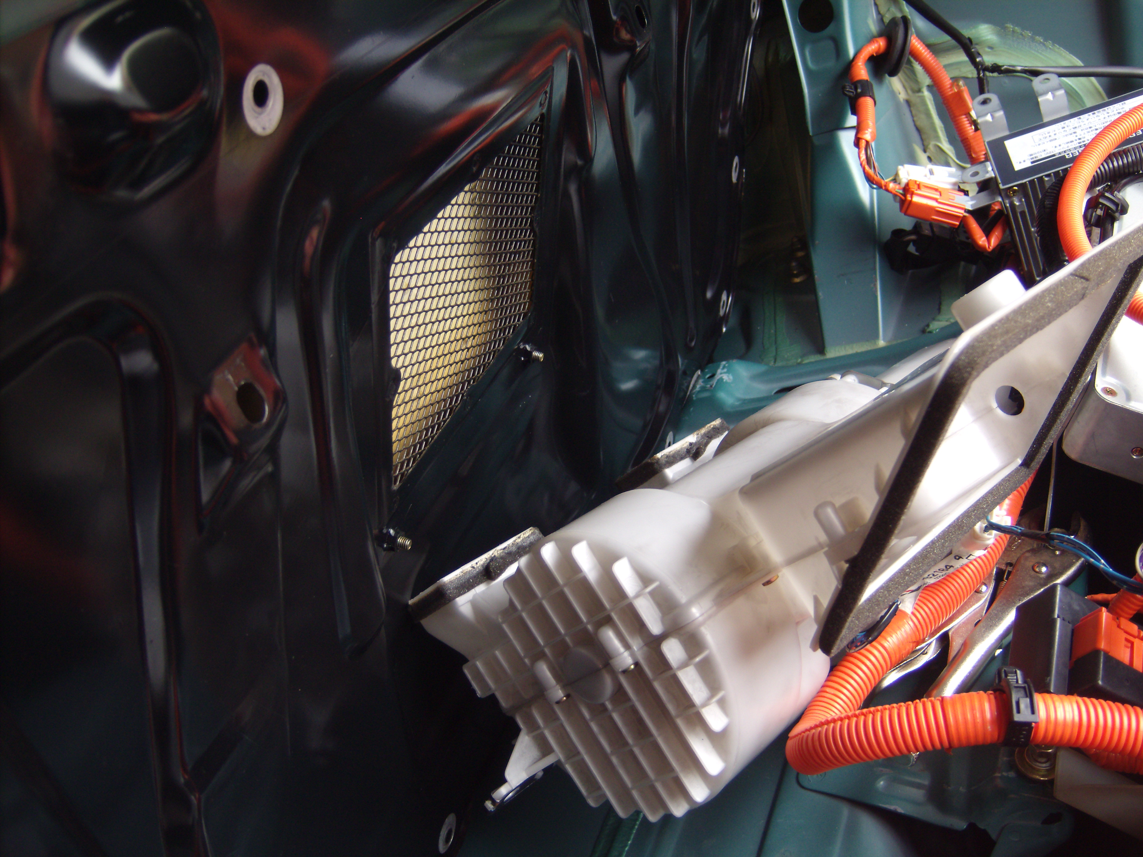
These are part of the motor assembly so we need to remove the inverter case to access these:
If you don't like the stereoscopic 3D just switch it off.
I also detail the removal of the invert unit for anyone contemplating it.
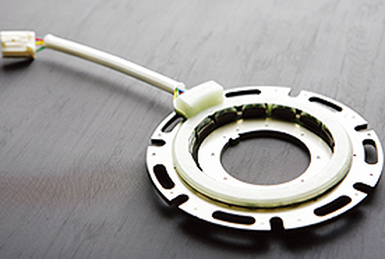
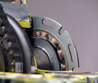
This is a "Variable Reluctance Resolver" or VR Resolver:
The resolvers in the Gen 1 Prius appear to be SinglSyn TS2208 pr similar
They are BRX resolvers, which means they have single input and sine/cosine output.
BRT resolvers have sine/cosine input and phase angle output.
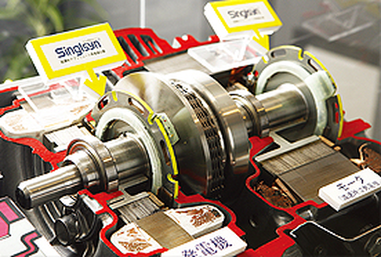
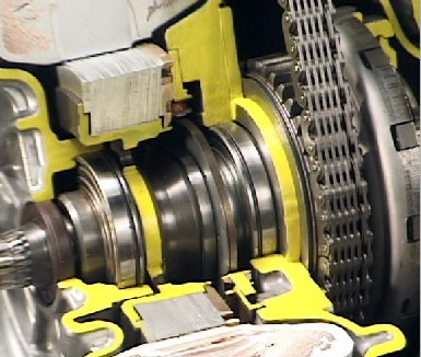
There are two in the transaxle, one for each motor/generator:
This is a cut away of MG1 resolver. The rotor not cut away.
MG2 resolver is clearly shown
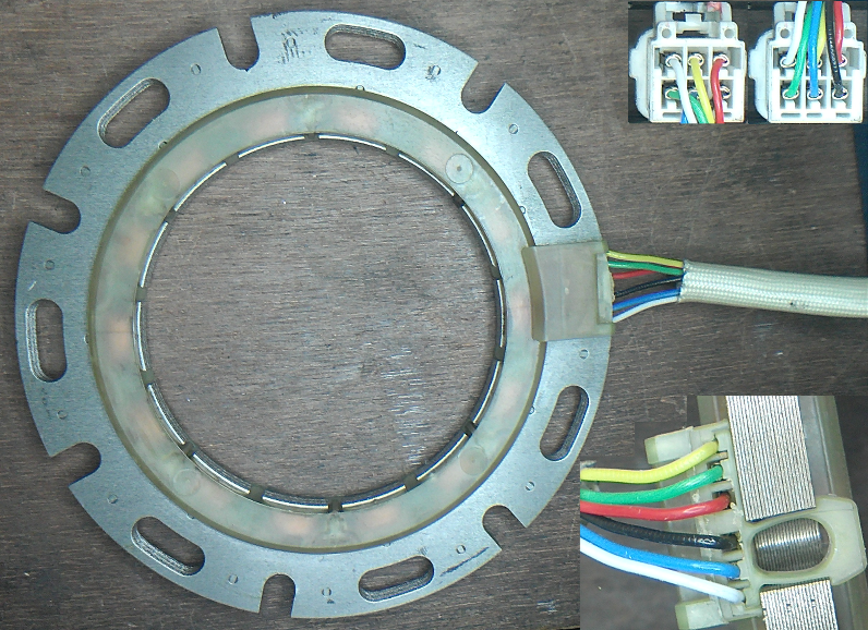
MG1 resolver removed from the MG1 being researched.
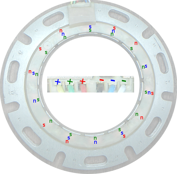
Some diagrams of the operation and wiring:
Rough model of the resolver which will be upgraded with more research.